Summary of ATMEGA8 PROGRAMMABLE CONTROLLER BOARD ELECTRONIC PLC CIRCUIT
Tiny Basic Controller (TBC) is a simple AVR-based PLC that interprets a Tiny-Basic dialect for home automation, control, and education. It provides 4 TTL discrete inputs, 4 TTL outputs (with LEDs), 2 analog inputs (10-bit ADC), 4 PWM outputs (10-bit, 5.4 kHz), and RS232 console at 57600 bps. Programs (≈2 KB+) are stored in flash and downloaded via RS232 terminal; JP1 protects against reflashing. The ATmega8 runs the interpreter and supports ADC, PWM (DAC command), bit operations, I/O commands, delays, scaling, and basic control flow statements.
Parts used in the Tiny Basic Controller (TBC):
- U3 ATMEGA8 microcontroller
- U1 TTL/CMOS to RS232 transceiver
- U2 5V voltage regulator
- LS1 buzzer (system caller)
- JP1 jumper (reflash protect)
- LEDs D1 ... D5
- Push button SW1 (RESET)
- Push buttons SW2 ... SW5 (test/debug)
- Connectors XP1 and XP2 (external circuits)
- Connector XP3 (ISP programmer, e.g., PonyProg)
- Crystal oscillator and capacitors for minimal AVR system
Tiny Basic Controller (TBC) is a simple device that can operate as a PLC (program logic controller) for home automation, control, etc. For example, this one can dial-up by modem to the remote computer and control the system, can control some processes, temperature regulation, battery charging, can be used for education and hobby purposes.
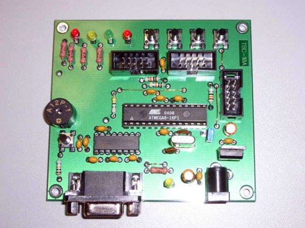
TBC is more analogue and discrete input / output and an RS232 interface to communicate with other devices and to reflect a control program.The control program is a text version of the BASIC language. The main task of the controller is to interpret BASIC commands. The TBC version of the BASIC language has the functions of discrete I / O, ADC and PWM. The view of controller PCB is shown below in the figure 1.
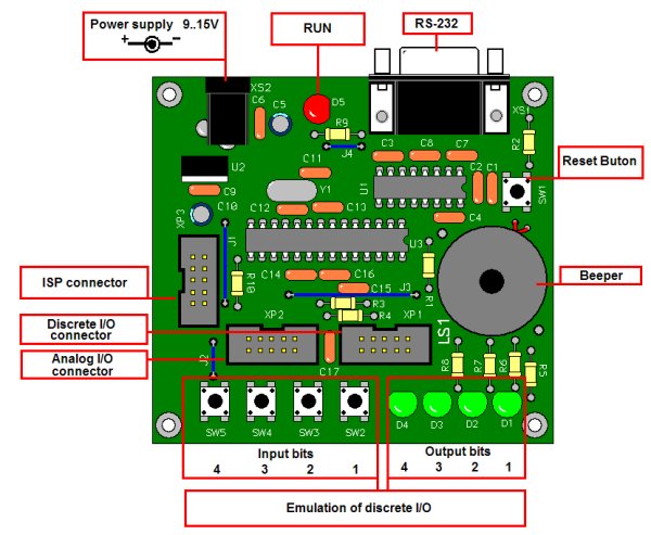 Figure 1
Technical details:
| 1. Number of discrete inputs TTL or 5V CMOS | 4 |
| 2. Number of discrete outputs TTL or 5V CMOS | 4 |
| 3. Number of analogue inputs 0 … 5V | 2 |
| 4. Number of PWM outputs | 4 |
| 5. Communication by RS232: | |
| Baud rate, bps | 57600 |
| Number of data bits | 8 |
| Number of stop bits | 1 |
| Parity bits | none |
| Flow control: | |
| 6.Flow control: | |
| Name BASIC program downloading stage | hardware |
| Horse operating stage | none |
| 7.The language of embedded interpreter | Tiny-Basic |
| 8.Size of the user program area, bytes, more than | 2000 |
| 9. Simple command operating time, less than uSec | 500 |
| 10 Basic program storage place | Flash program |
10-bit PWM has a frequency of 5.4 kHz.
10-bit ADC Conversion time is about 30 usec, but real sampling depends on the program loop.
Current through discrete outputs must be limited up to 20 mA.
Note that an LED is connected to each of discrete outputs. The current is about 8 mA per LED
The schematic controller is shown in Figure 2.
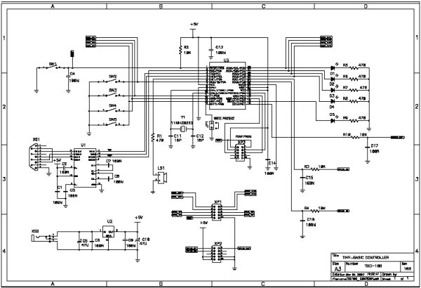
Figure 2
Short description of schematic:
U3 is AVR microcontroller ATMEGA8.
The control program with thr BASIC interpreter for this controller is programmed by ISP after PCB is assembled. The firmware can be downloaded from here . We used the PonyProg programmer connected via the connector XP3. The Figure 3 shows how the fuses should be programmed.
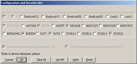
Figure 3
U1 is TTL / CMOS <-> RS232 transceiver
U2 is 5V voltage regulator
LS1 is a buzzer. This one can be any system caller. Make sure that the current drawn by pin U3: 5 is limited to 20 mA.
To prevent the user program from erasing there is the jumper JP1. When it is closed re-flashing of the user program is disabled.
LEDs D1 … D4 indicate state of discrete outputs.
LED D5 indicates the program state. When the program is run the D5 is turned on. When D5 is turned off it means that the program is stopped or waiting for the input (INPUT command) or a delay (DELAY command).
Push button switch SW1 controls the RESET line of microcontroller ATMEGA8.
Push button switches SW2 … SW5 are used as test signals for debug purposes.
To connect external circuits there are connectors XP1 and XP2.
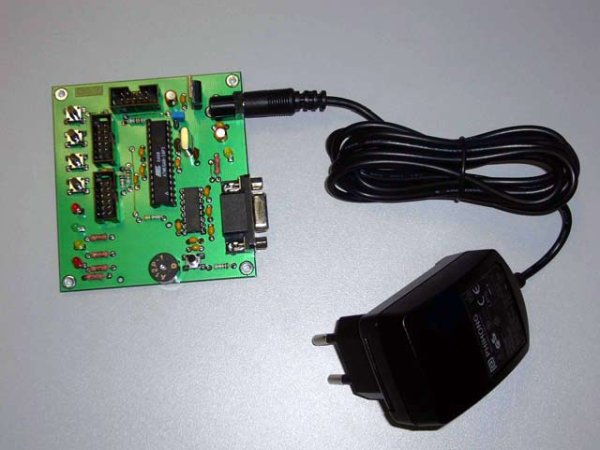
TBC as a Black Box is shown on the figure 4.
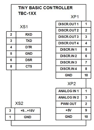
Figure 4
It is a good idea to use a socket for U3 then the full PCB can be used as a programmer for a minimal system based on TBC. The minimal system consists of AVR-microcontroller, three capacitors and a crystal oscillator plus the user circuit, of course.
The PCB layout is shown in the figure 5
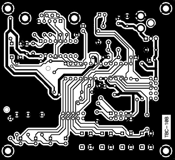
Figure 5
The assembly diagram is shown below
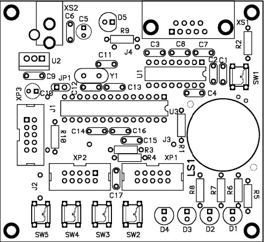
Figure 6
Specific pins control commands and commands SCALE and REM were added to the Tiny Basic specification.
Console input / output is the same as it was years ago. We can now use a PC with running HyperTerminal as a console. A console is required when programming or if the program uses the INPUT or PRINT commands.
HyperTerminal or other terminal application must be set up as shown below:
| Baud rate | 57600 bps |
| Data / Stop bits | 8/1 |
| Parity | None |
| Flow Control | Hardware |
| Terminal emulation | ANSII / VT100 |
| Add sent CR with LF |
User program downloading
There are two ways to download. The first one is using the text file option option of the terminal. The second way is to use paste from the clipboard if you are using Windows HyperTerminal, for example:
1.Make sure that jumper JP1 is open.
2.Connect TBC to PC by RS232 cable.
3.Power it up.
4.Start terminal application.
5.Press the reset button on the TBC.
You now have one second to send SPACE or ENTER from the terminal. SPACE is for download BASIC application and ENTER is for current BASIC program. When the one second interval expired the current application starts. If you hurry to send SPACE, after the reset button is pressed, you will get the message “Reflash …” on the terminal of the terminal. You must send the program text by paste from the clipboard or text sending option. TBC outputs a “W” symbol for each 64-bytes blocked flashed during programming operation. If you press SPACE instead of Enter, just list the current program, just press the reset button to cancel the reflash operation. The method of working with the TBC and a console is shown below. At first you should create program text in the notepad. Then copy the whole text to the clipboard.
Figure 7
. There is a one second interval to send the SPACE symbol to the TBC to activate the downloading process.
Figure 8
Send text by terminal We can see the re-flashing process
Figure 9
When the re-flashing process is finished, the message “OK” is sent. To start the application, press the reset button, the application will run. You can see that you only need to have the simplest editor and terminal in your kitchen to program the TBC. You can use a palm on your PC as well. A PDA console is shown below:
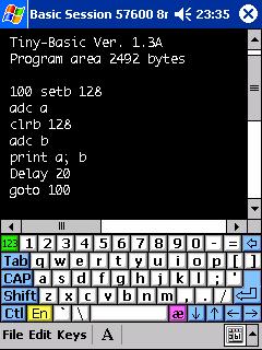
Figure 10
Controller version of Tiny Basic
Numbers
All numbers are signed integers and must be between -32767 and 32767.
Variables
There are 26 variables denoted by the letters A through Z. These are represented internally as 16-bit, two-complement integers.
Arithmetic operators
All operations are performed to 16 bits of precision. Arithmetic operations which overflow 15 bits of magnitude will cause an error message.
The arithmetic operators are:
+ addition.
– subtraction
* multiplication.
/ integer division (note that 14/5 = 2).
% remainder from division (14 MOD 5 = 4).
& bit-wise logical AND (3 AND 6 = 2)
| bit-wise logical OR (3 or 6 = 7) Arithmetic operations result in a value between -32767 and 32767.
Compare Operators:
> bigger than.
<less than.
= equal to.
Note that comparison operators can not be used in expression.
Expressions
Expressions are created with numbers and variables with arithmetic operators between them. Operations are performed with three levels of precedence. The first step is to perform Unary operations (+, -), then Multiplicative operations (*, /,%, &), additive operations (+, -, |). Within each precedence level, the value of an expression is computed from left to right. Parentheses can also be used to alter the order of assessment.
Labels
Label is a set from 1 to 3 digits. Labels must be set before line that is a point to jump or is a start line of subroutine.
Syntax:
| linefeed (LF) and carriage return (CR) added to the output | |
| There is PRINT | Send variable in decimal form to the console and add CR and LF |
| PRINT “message” | Send message to the console and add CR and LF |
| PRINT x, y, z, | Send list of variables, comma number of spaces to set output to the next position of tabulation. Comma at the end of line cancel add CR and LF |
| PRINT x; y; z; | Send list of variables and string. Semicolon allows output more than one variables or strings at one line. Semicolon at the end of line cancel add CR and LF |
| PRINT “$”; y; | $ -version of PRINT command. It allows sending single symbol by symbol code. Semicolon at the top of the line and add CR and LF |
Syntax:
| INPUT | Output “?” And wait for input value. Puts value to variable X after receiving CR |
| INPUT “prompt”, there is | Output prompt and waiting for input value. Puts value to variable X after receiving CR |
| INPUT “$”, there is | Waiting for a single symbol. Put symbol code to variable C |
Syntax:
| IF condition THEN expression | If condition is true expression is calculated |
| IF condition THEN GOTO label | If the condition is true, go to line with label |
| IF condition THEN GOSUB label | If condition is true subroutine with label is called |
Syntax:
| FOR var = start_value TO end_value REM Put statements here NEXT |
Execute a number of times. number = end_value – start_value + 1 |
Syntax:
| GOTO label | Jump to the label. |
Syntax:
| GOSUB label | Call subroutine labeled as label |
Example:
REM Example
|
Syntax:
| RETURN | Return from subroutine |
Syntax:
| END | Stop execution |
Syntax:
| There’s ADC | Read current channel of ADC and put value into variable |
Syntax:
| DAC expression | Output result of expression to PWM channel |
Syntax:
| SETB expression | Set bitwise |
Syntax:
| CLRB expression | Clear bit is the result of expression |
Syntax:
| TSTB variable, expression | Read bit value is the value of the variable |
Syntax:
| DELAY variable, expression | Form delay in msec is the result of expression |
Syntax:
| SCALE variable, multiplier, divider | Operator of scaling. Does actions: 1.TMP32 = variable * multiplier 2.variable = TMP32 / divider |
Syntax:
| STOP | Stop operator. Use for debug purpose in simulator |
Syntax:
| REM Just a comment | Comment operator. Interpreter does not execute this line |
TBC system bits
Input bits
| Bit number |
Description |
|---|---|
| 1 | Discrete input # 1 |
| 2 | Discrete input # 2 |
| 3 | Discrete input # 3 |
| 4 | Discrete input # 4 |
| 126 | Flag that signals about data in the console buffer |
Example 1. The program does an infinite cycle that reads the state of the console
100 TSTB X, 1 IF X = 1 THEN PRINT "1" IF X = 0 THEN PRINT "0" GOTO 100 |
Example 2. The program reads the state of the console and executes some background tasks. If there is a data in the console buffer, it execute the INPUT command to read the data and output it to the console.
10 rem Do something else as background task tstb a, 126 if a = 0 then goto 10 input "$", b print "$"; b; goto 10 |
Output bits
| Bit number |
Description |
|---|---|
| 1 | Discrete output # 1 |
| 2 | Discrete output # 2 |
| 3 | Discrete output # 3 |
| 4 | Discrete output # 4 |
| 127 | Sound enabled / disabled – 1/0 |
| 128 | Switch to ADC channel: 0 – channel # 1 1 – channel # 2 |
Example. The program forms double beep
GOSUB 200 GOSUB 200 END 200 SETB 127 DELAY 100 CLRB 127 DELAY 100 RETURN |
Read more Detail: http://www.cqham.ru Atmega8 plc circuit alternative link: atmega8-programmable-controller-board-electronic-plc-circuit.rar alternative link2 alternative link3
- How many discrete inputs and outputs does the TBC have?
The TBC has 4 discrete TTL/5V CMOS inputs and 4 discrete TTL/5V CMOS outputs. - What communication interface and settings are used to connect TBC to a PC?
TBC uses RS232 at 57600 bps, 8 data bits, 1 stop bit, no parity, hardware flow control, terminal emulation ANSII/VT100, and append CR with LF. - How do you download a BASIC program to the TBC?
Open JP1, connect RS232, power up, start terminal, press RESET, then send SPACE within one second to enter reflash mode and paste or send the BASIC text; TBC outputs W for each 64-byte block and OK when finished. - Where is the user BASIC program stored in the TBC?
User BASIC programs are stored in the flash program memory of the ATmega8. - What ADC and PWM capabilities does the controller provide?
The TBC provides two 10-bit ADC channels (conversion ~30 usec) and four 10-bit PWM outputs at 5.4 kHz. - How much current can each discrete output source and what about LEDs?
Discrete outputs must be limited to 20 mA; each output has an LED drawing about 8 mA. - What language does the embedded interpreter use and how large is program memory?
The embedded interpreter uses Tiny-Basic and the user program area is more than 2000 bytes. - What is the purpose of JP1 jumper?
When JP1 is closed, re-flashing of the user program is disabled to prevent accidental erasure. - How does the TBC indicate program running or waiting states?
LED D5 indicates program state: on when running; off when stopped, waiting for INPUT, or during DELAY. - Can the TBC be used as a minimal AVR programmer or minimal system?
Yes; using a socket for U3 the PCB can serve as a programmer, and the minimal system requires the AVR, three capacitors, and a crystal plus the user circuit.