Summary of ATMEL ATMEGA8 VIA USB CONTROL CIRCUIT
Summary: The article describes an ATmega8-based USB control board that replaces earlier ATTINY2313/PIC16F88 USB-UART designs. It controls 15 relay outputs with observation LEDs, diode protection, and a ULN2804 output buffer. The board is powered by an external supply and a 3.3V regulator for the ATmega8 running at 12 MHz with provided hex firmware; ASM sources from the web caused compile errors. The design works reliably though USB toggling is slightly slow.
Parts used in the ATmega8 USB Control Circuit:
- ATmega8 microcontroller
- ULN2804 output buffer
- Relays (15)
- Diodes for relay protection
- LEDs for output observation (at least 3 used)
- External power supply
- 3.3V voltage regulator (integrated)
- PCB and enclosure (board and cover)
- USB connection hardware
- Associated passive components (resistors, capacitors)
Hi, I have done recently attiny2313’l usb application (ATTINY2313 PIC16F88 USB UART converter circuit) then one needs at this time on I did with ATmega8. RS232 portion of the circuit 15 disuse I /… Electronics Projects, Atmel Atmega8 via USB Control Circuit “atmega8 projects, avr project, microcontroller projects, “

Hi, I have done recently attiny2313’l usb application (ATTINY2313 PIC16F88 USB UART converter circuit) then one needs at this time on I did with ATmega8. RS232 portion of the circuit 15 disuse I / O pin with a control board that communicates via usb I designed.
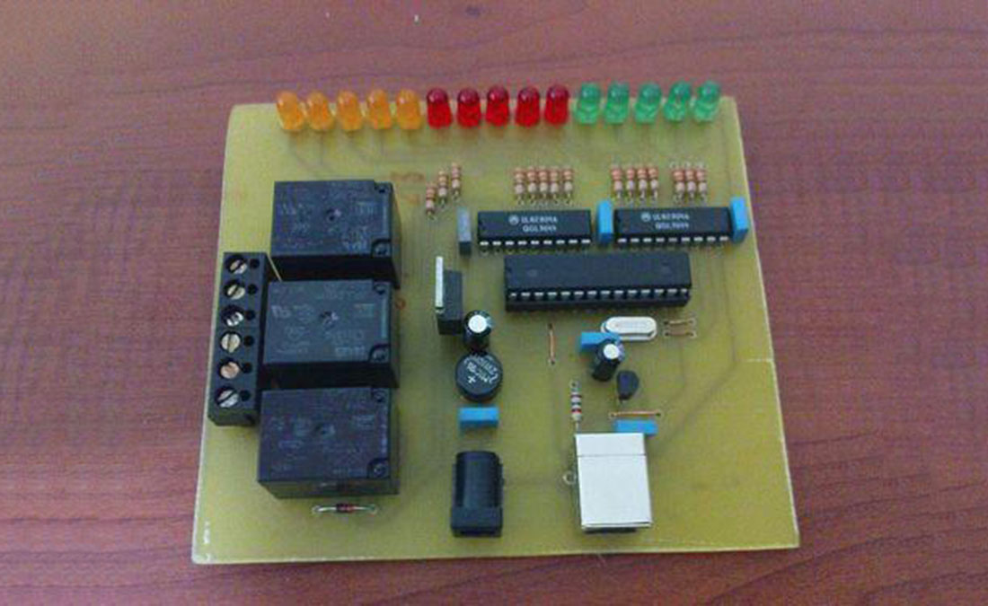
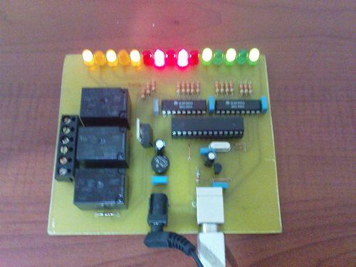
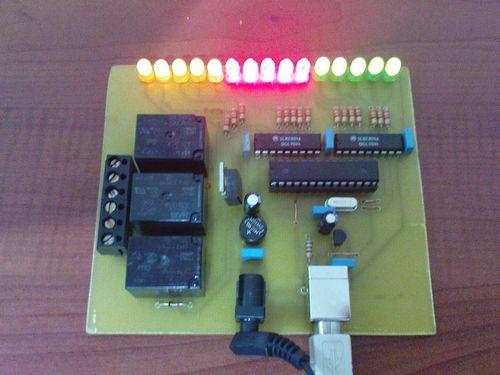
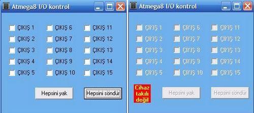
Available in 15 out of 15 relay circuit on a plaque by Cover with too much space. Relay outputs to observe instead I added diodes. We also work with 1,2,3 led to the exit to observe’ve added 3 relays. Circuit fine çalışıyor.atmega8 ‘s usb output due to the hassle of opening and closing process is a bit slow, but speed is sufficient for the control board.
Atmega8 to strengthen the output to the output buffer uln2804’ve added. On the circuit diodes, relays, uln2804 ATmega8 with elements such as external power supply from the USB USERNAME 3.3v regulated with integrated fed. This combination works very well with ATmega8 ATmega8 3.3v 12MHz speed asm code avr309 application note available in the Docs give errors when compiling asm file I found on the internet because I have installed a hex file works fine.
ATMEGA8 USB CONTROL CIRCUIT TEST
USB control circuit schematic pcb code files: atmel-atmega8-via-usb-control-circuit.RAR
- What microcontroller is used in the USB control circuit?
The circuit uses an ATmega8 microcontroller. - How many relay outputs does the board provide?
The board provides 15 relay outputs. - Does the design include protection for the relays?
Yes, diodes are added for relay protection. - Is there an output driver used with the ATmega8?
Yes, a ULN2804 output buffer is used to strengthen outputs. - What power supply and voltage regulation are used?
The board uses an external power supply and an integrated 3.3V regulator for the ATmega8. - What clock speed does the ATmega8 run at?
The ATmega8 runs at 12 MHz in this design. - Are observation LEDs included on the board?
Yes, LEDs are added to observe outputs; at least three LEDs were used with three relays. - Is there firmware provided for the circuit?
Yes, a working hex file firmware is available; ASM sources found online caused compile errors. - How is the USB responsiveness described?
The USB toggling/opening-closing process is a bit slow but sufficiently fast for the control board.