Summary of Atmel AVR Programmer USB Circuit Atmega8
Summary: This article describes a streamlined AVR Doper USB ISP programmer for Atmel AVR microcontrollers (ATmega8). It covers schematic and PCB modifications using Eagle, single-sided board etching, component list, ISP pinout, firmware and driver sources, fuse settings, and testing notes. The design fits in an Altoids tin and supports HID mode and AVRDude compatibility.
Parts used in the AVR Doper USB Programmer:
- Atmel ATMEGA8-16PI
- 74HC126N Quad Buffer
- 12 MHz Crystal HC49/US
- 28 pin IC socket
- 14 pin IC socket (optional)
- Resistor Carbon Film 68 Ohm 1/4 Watt 10% (2)
- Resistor Carbon Film 270 Ohm 1/4 Watt 10%
- Resistor Carbon Film 1K Ohm 1/4 Watt 10% (2)
- Resistor Carbon Film 10K Ohm 1/4 Watt 10% (5)
- Resistor Carbon Film 2K2 Ohm 1/4 Watt 10%
- Resistor Carbon Film 22K Ohm 1/4 Watt 10%
- Resistor Carbon Film 33K Ohm 1/4 Watt 10%
- Ceramic Radial Capacitor 22pF 50V 5% (2)
- Ceramic Radial Capacitor 0.1uF 50V 10% (2)
- Electrolytic Radial Capacitor 4.7uF 16V 20%
- 3.6 Volt Low Power Zener Diode (2)
- 5×2 Pin Gold Straight Header .100″
- 2 x 1 Pin Gold Straight Header .100″ (3)
- Shunt .100″ (3)
- Red LED
- USB Connector
- Single-sided Copper Clad Board 1 oz. 3.5″ x 2.125″
- Altoids 50g Tin
Via the USB port of your computer that you can program Atmel series microcontrollers ISP port with stylish design a programming circuit. Prepared with eagle pcb circuit usb programming. are schematic drawings. To use the circuit to inspectors ATmega8 avr-doper-mega8-12mhz_a.hex need to download the file.
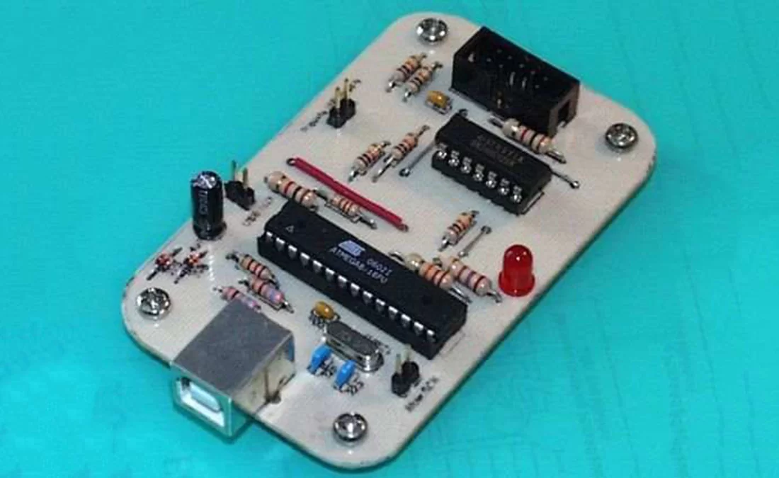
Simplified Version of AVR Doper USB Programmer simple inexpensive Parallel ISP programmer has done the job since I started working with AVR’s, but it definitely has its problems. It doesn’t work with some computers, it is slow, it is unreliable and it requires a parallel port which is getting less common. USB seemed the natural progression. I selected the AVR Doper project by Objective Development as the base for the new programmer.
Below is a 3D model of the streamlined AVR Doper created in POV-Ray using Eagle3D. I only wanted to build an ISP so I was able to lose many of the components related to HVSP. I rounded the edges and scaled the board to fit in an Altoids tin.
I modified the Objective Development schematics and circuit board using the free version of CadSoft Eagle. I designed the board to be single-sided but it does require 4 bridges.
I etched the circuit board using a laser printer, glossy photo paper, hydrogen peroxide and muriatic acid. Here are my etching notes in PDF format and this is a great website that further details the process.
Parts List:
Atmel ATMEGA8-16PI 1
74HC126N Quad Buffer 1
12 MHz Crystal HC49/US 1
28 pin IC socket 1
14 pin IC socket (optional) 1
Resistor Carbon Film 68 Ohm 1/4 Watt 10% 2
Resistor Carbon Film 270 Ohm 1/4 Watt 10% 1
Resistor Carbon Film 1K Ohm 1/4 Watt 10% 2
Resistor Carbon Film 10K Ohm 1/4 Watt 10% 5
Resistor Carbon Film 2K2 Ohm 1/4 Watt 10% 1
Resistor Carbon Film 22K Ohm 1/4 Watt 10% 1
Resistor Carbon Film 33K Ohm 1/4 Watt 10% 1
Ceramic Radial Capacitor 22pF 50V 5% 2
Ceramic Radial Capacitor .1uF 50V 10% 2
Electrolytic Radial Capacitor 4.7uF 16V 20% 1
3.6 Volt Low Power Zener Diode 2
5×2 Pin Gold Straight Header .100″ 1
2 x 1 Pin Gold Straight Header .100″ 3
Shunt .100″ 3
Red LED 1
USB Connector 1
Single-sided Copper Clad Board 1 oz. 3.5″ x 2.125″ 1
Altoids 50g Tin 1
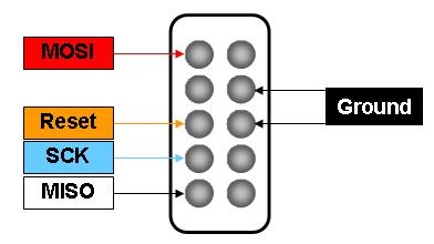
Here is the pinout for the 10 pin ISP jack.
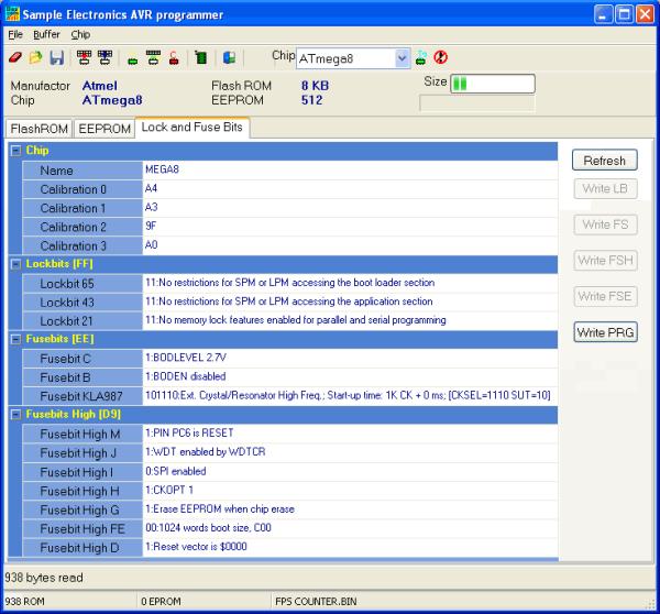
The AVR .hex code, USB .inf driver and other info is available from the AVR Doper Project site. Fuse Settings: CKSEL=1110 SUT=10 (Screenshot of Bascom Fuse Settings)
I have successfully tested the programmer with the 2008-11-27 firmware. I created a slightly modified version of the 2008_11_27 AVR Doper firmware to bypass the upgrade warning in AVR Studio. Here are my upgrading notes. The USB programmer can be used to upgrade itself if you have a spare ATMega8 chip.
We recommend that you use AVR-Doper in HID mode instead, which has no such problem. This mode is supported by AVRDude. More information about interface modes and their relative advantages can be found in the project description.
AVRDude 5.3.1 and higher now supports the AVR Doper programmer. SinaProg is an excellent AVRDude GUI that also supports the AVR Doper.
Source: Atmel AVR Programmer USB Circuit Atmega8
- What microcontroller is used in this USB programmer?
The project uses an Atmel ATMEGA8-16PI microcontroller. - Can the board be single-sided?
Yes, the board was designed to be single-sided but requires four bridges. - What firmware version was successfully tested?
The programmer was successfully tested with the 2008-11-27 firmware. - Where can I get the AVR hex code and USB driver?
The AVR .hex code, USB .inf driver and other info are available from the AVR Doper Project site. - What fuse settings are recommended?
Fuse settings listed are CKSEL=1110 and SUT=10. - Which software supports AVR Doper?
AVRDude 5.3.1 and higher supports the AVR Doper; SinaProg is an AVRDude GUI that also supports it. - Is there a mode that avoids upgrade warnings in AVR Studio?
The article recommends using AVR-Doper in HID mode to avoid such problems. - Can the USB programmer upgrade its own firmware?
Yes, the USB programmer can be used to upgrade itself if you have a spare ATMega8 chip.