Summary of ATtiny Dev Board / Tinyduino
This article details the construction of a compact ATtiny Dev Board, designed for easy prototyping with ATmel microcontrollers. It features a built-in voltage regulator, ISP header, and power selection switch. The guide outlines necessary parts like a perforated PCB, capacitors, resistors, a 7805 regulator, and various headers, alongside tools such as a soldering iron and wire strippers. Instructions cover cutting the PCB, bending components, and soldering techniques to assemble the board efficiently.
Parts used in the ATtiny Dev Board:
- 1x Perforated PCB
- 2x 1x4 Female headers
- 2x 1x3 Male pin
- 2x 100nF Ceramic capacitor
- 1x Resistor 10k ohm
- 1x Resistor 220 ohm
- 1x Slide Switch (SPDT)
- 1x Momentary push button
- 1x LED 3 or 5mm any color you like
- 1x 8 Pin DIP socket
- 1x 7805 Voltage regulator
- 1x Terminal block
- Some wire
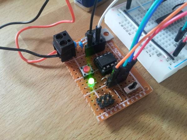
This is an ATtiny Dev Board. Designed for the ATtiny line of microcontollers from atmel. Its made to be small, simple to build and easy to use.
This board has following features:
– Female headers for easy prototyping
– Build-in 1A 5V voltage regulator
– 8-Pin socket to change out microcontrollers
– ISP-Header for programming
– Power selcet switch, using voltage regulator or the USB power of the programmer
– Reset button
– Power on LED
This board has following features:
– Female headers for easy prototyping
– Build-in 1A 5V voltage regulator
– 8-Pin socket to change out microcontrollers
– ISP-Header for programming
– Power selcet switch, using voltage regulator or the USB power of the programmer
– Reset button
– Power on LED
Step 1: Required Parts / Tools
Parts:
1x Perforated PCB
2x 1×4 Female headers
2x 1×3 Male pin
2x 100nF Ceramic capacitor
1x Resistor 10k ohm
1x Resistor 220 ohm
1x Slide Switch (SPDT)
1x Momentary push button
1x LED 3 or 5mm any color you like
1x 8 Pin DIP socket
1x 7805 Voltage regulator
1x Terminal block
1x Some wire
Tools:
– Soldering iron
– Solder
– Helping Hands
– Box cutter
– Wire stripper
– Wire cutter
– Tweezers
– Pliers
Step 2: Score and Snap Your PCB
My PCB was alrady 18 pads wide so i only need to shorten the PCB to 11 pads long, i did this by counting down the 11 rows and started to score the 12 row with a boxcutter (BE CAREFUL). After 5 to 10 passes i snaped the board in half. If your board is wider as mine you need to do the same for the other side too but this time 18 pads instead of 11. If done corrctly the borad shoud look like the board in Step 1
Step 3: Bend and Solder Resistors
The 10k ohm resistor is bend so that it spans 4 holes. And the 220 ohm resistor is bend to span 5 holes. Solder them in as seen in the picture. And use the PCB layout as reference. Its helpful to own Helping hands so its easier to solder, it’s best to solder one leg first then applying pressure to the part and reheat the joint so that the part aligns with the PCB. Now you can solder the second leg. You maybe want to use some kind of tool to apply pressure since the part could get hot quite quickly.
Read more: ATtiny Dev Board / Tinyduino
- What are the main features of this ATtiny Dev Board?
The board includes female headers for prototyping, a built-in 1A 5V voltage regulator, an 8-Pin socket for changing microcontrollers, an ISP-Header for programming, a power select switch, a reset button, and a power on LED. - How do I prepare the PCB before soldering?
You must score the PCB with a box cutter along the desired pad count lines and then snap it in half to achieve the correct length. - Which resistors are required and how should they be bent?
A 10k ohm resistor should be bent to span 4 holes, while a 220 ohm resistor should be bent to span 5 holes. - Can I change the microcontroller on this board easily?
Yes, the board features an 8-Pin socket specifically designed to allow users to change out microcontrollers. - What tools are needed to build this project?
Required tools include a soldering iron, solder, helping hands, a box cutter, wire stripper, wire cutter, tweezers, and pliers. - How does the power select switch function?
The switch allows the user to choose between using the voltage regulator or the USB power from the programmer. - What is the recommended method for soldering small components?
Solder one leg first, apply pressure to align the part with the PCB, reheat the joint, and then solder the second leg. - Is there a specific type of LED required for this board?
You can use any color LED that is either 3mm or 5mm in size.