
Summary of ATTiny2313 Multi-mode LED Matrix Clock
This hobby project builds a multi-mode 12-hour clock using an ATtiny2313 microcontroller and an 8x8 LED matrix. It features row-column multiplexing, a single tactile button for control, and low-power sleep modes. The design omits current-limiting resistors to save space and uses the internal oscillator, requiring manual calibration every few days.
Parts used in the ATTiny2313 Multi-mode LED Matrix Clock:
- attiny2313v microcontroller
- 8x8 LED matrix display (common cathode)
- tactile button
This is a mutli-mode clock project based on attiny2313. it employs a 8×8 led matrix as display. with the limited resolution, this 12 hour clock shows time in 6 different modes.
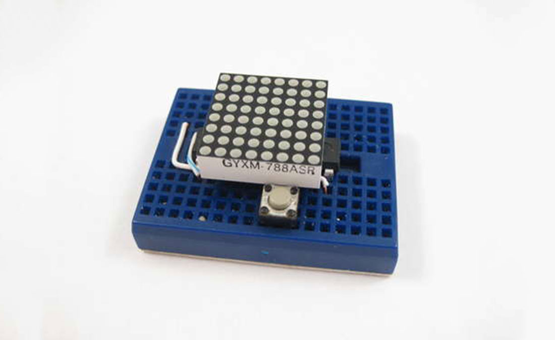
The circuit employs row and column multiplexing to drive the leds, one row at a time, this gives a 12.5% duty cycle when “sets” of leds (8 of them in each of the 8 rows) are turn on briefly. Current limiting resistors are eliminated to save breadboard estate and as we are not constantly driving individual leds, they are not going to be damaged.
The control (user interface) is also arranged so that we only use one tactile button for input. the firmware capture long button presses (press and hold) for menu rotation and normal button presses for menu selection.
This is a hobby project and the clock is only as accurate as your internal oscillator calibration. I had not use a crystal in this project as doing so will upset the “matrix on top of mcu” breadboard layout. a crystal can be used to increase accuracy on a alternate breadboard layout (or pcb). With software compensation, i can achieve may be within 2 minutes off a day. I would need to adjust the time every 3 or 4 days
Step 2:Features and Parts

features
* minimal components, 3 parts
* battery operated from 3V to 5V
* use of watchdog timer to keep time, power-down sleep mode takes about 1uA power
* calibration allow setup of seconds to gain for each hour
* this is a 12H clock, not 24H and has no AM/PM indicator
* not very accurate, planning to add RTC chip
parts list
* attiny2313v (v is low power version that works with 3V)
* 8×8 LED matrix display (red works best on 3V power)
* tactile button
led matrix pinout
the 8×8 led matrix has dot size of 1.9mm and is of common cathode, if you have common anode type, you can change a few lines in the code for adoption. see the following diagram and see if you have the right pin-outs. it appears they are quite common and if you purchase via ebay most suppliers have the same pin-out even if the model number is different.
. . . . . C8 C7 R2 C1 R4 C6 C4 R1 . . . . top row of pins (C is column, R is row)
. . . . . R5 R7 C2 C3 R8 C5 R6 R3 . . . . bottom row of pins
the 8×8 led matrix has dot size of 1.9mm and is of common cathode, if you have common anode type, you can change a few lines in the code for adoption. see the following diagram and see if you have the right pin-outs. it appears they are quite common and if you purchase via ebay most suppliers have the same pin-out even if the model number is different.
For more details, click: ATTiny2313 Multi-mode LED Matrix Clock
- How does the clock drive the LEDs?
The circuit employs row and column multiplexing to drive the LEDs one row at a time. - Can I use a common anode LED matrix?
Yes, you can change a few lines in the code to adapt it for a common anode type. - Why are current limiting resistors not used?
They are eliminated to save breadboard estate since individual LEDs are not constantly driven. - What is the power consumption during sleep mode?
Power-down sleep mode takes about 1uA of power. - How accurate is this clock without a crystal?
It may be within 2 minutes off a day with software compensation, but requires adjustment every 3 or 4 days. - Does the clock support 24-hour time format?
No, this is a 12H clock and has no AM/PM indicator. - Can a crystal be added later?
A crystal can be used to increase accuracy on an alternate breadboard layout or PCB.
