In this post, we will learn about Attiny85-Decision-Box-V2.0: After seeing my first Attiny85 based “Decision box” had become quite popular I decided to make a second version with more improvements using common materials so everyone can build it.
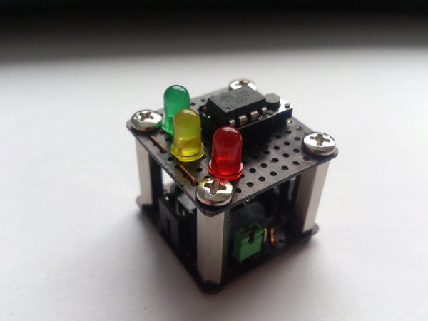
The main difference between the first and second version are the materials they’re made of, while the first box was made out of wood, this version has two perforated boards stacked together with hex spacers and screws, and connected by pin headers and connectors. This makes it more modular, robust and easy to assemble. Another difference is the LED’s, in this version I used three LEDs instead of a single common cathode red-green LED, not just because I had more space to put them, but also because it has allowed me to be more creative when making the program.
Steps how to make Attiny85 Decision Box V2.0
Step 1: Materials:
- Attiny85
- 8pin chip socket
- Coin battery holder
- CR2032 Coin battery
- Perforated board
- Pushbutton
- Hex spacers (around 2cm, 3/4 inch)
- 8 screws for the spacers
- Long pin headers
- Connectors for the pin headers
- Red, green and yellow LEDs
- Copper wire
- 120Ohm resistor
- 10kOhm resistor
You’ll also need a soldering iron.
Step 2: The Circuit:
The circuit is quite simple, but assembling it together in two different planes can be a bit tricky.
This circuit runs on 1mA when idle and around 5-6mA when using the LEDs, so assuming the coin battery has a capacity of 200mAh, it should run for a week before draining the battery in case it’s left on.
Step 3: Assembling the Cube.
Start by cutting two squares of 11×11 pads, we need an odd number of pads because components like the button occupy an odd number of them, and by making this we make sure they are symmetrical respect to the centerline. I also bent the pins of the chip socket so it could fit in a 4×3 group, instead of the usual 4×4, this way it’s properly aligned and vertical. You can also connect it in a horizontal way, but making the connections could be harder. If you find it hard to do this you can always use a 13×13 boards, or 12×12, if your button occupies 4×4 pads.
Make a hole at the center of the 2×2 pad groups located at the edges, the hex spacers will be placed there, the holes need to be big enough for the screws to fit in. Use a precision tool for better accuracy.
Once the holes are made put the components on the board. I’ve traced the circuit with colors according to the schematic so you don’t get lost when soldering it.
Notice that there is solder under the blue resistor (10kOhms) connecting the LEDs and the chip to the ground.
For the main switch I used a pair of pin headers and a bridge connector from a computer, you can use a small through-hole switch or even a tilt switch.