Summary of Attiny85 As a Step/Dir Stepper Motor Controller
### Article Summary This article details a DIY project creating a low-cost software stepper motor controller using an Attiny85 microcontroller. It addresses the high cost and complexity of commercial hardware controllers by proposing a solution that translates simple Step/Dir signals into precise motor movements. The author overcomes the Attiny85's limited pin count (typically 6 usable IO pins) by repurposing the reset pin as an I/O line, enabling the chip to control a stepper motor without expensive external drivers.
Parts used in the Attiny85 Stepper Motor Controller:
- Attiny85 Microcontroller
- Stepper Motor
- Transistors (for power amplification)
- Step Signal Interface
- Direction Signal Interface
Somewhere in Greece, someone did something never done before…
Seen those things before?
Thing: 1
Thing: 2
Thing: 3
Oh, you have! You bought one of them you say? Oh… Don’t worry, I did too.
They did the job, yeah. But we paid for them much. Really much. And while our whole project would cost less than 60 bucks or euros without them, they slapped as in the face, then took our money and ran … our precious motors…
The revenge has come…
We all love steppers! They do some really nice things.
1) They ran great CNC systems, that make all kinds of goods!
2) They play music, sometimes better than humans!
Basically They do only those two things but they are enough…
We, people, often control them via computers or microcontrollers and make them do those nice things and live happily together.
Steppers differ from DC motors structurally and behaviorally. They have 4 control wires (instead of 2) and, in order to make the rotor move, you have to apply voltage to some combinations of them, and change the combinations over small (really small) time intervals (maybe every 0.01 seconds or less).
Why is that, you may ask. But it is for PRECISION! The god of productive machinery! Every time you drive the stepper wires with a correct combination the rotor moves by a certain amount of degrees… That way you can tell where the rotor is by just measuring how many such voltage combinations you have applied to the motor. Knowing the position of something without any kind of feedback is Really Something!!!
(You can read much more here. There is a decent explanation of microstepping inside. the thing that this project CAN’T do at the time of writing)
Step 2: Stating the Problem…
So, as you may have realized, steppers are a hassle to use and control. All those wires, voltages, combinations and degrees/step are simply too much for a human to control.
And when it comes to CNCing, computers find it hard too. It is difficult even for computers, to control all the above combined with the needs of a CNC device: steady velocity, measured acceleration, simultaneous motion and taking a note of every rotor at any given time.
But when we face problems with multitasking we have the most elegant solution (when it comes to engineering):
Split the tasks to more than one worker. And that happened. The computer got rid of anything that has to do with voltages and combinations of wires. A simple interface was given to the computer so it could communicate with the motor. An interface that only contains 2 signals. A Step signal that every time it goes High (edge triggering) the motor has to move 1 “step” and a Direction signal that decides at which direction would be the step (ex: High for CW, Low for CCW).
So this is the Step/Dir interface.
Now a second device was needed to translate the Step/Dir signals to actual 4-wire signals, move the motor and generally do the hard work. This device is the Stepper Controller. And as of today, only one type of this device exists commercially: the hardware one. It uses H-bridges along with some kind of hardware logic, and other tricks ending up to quite complicated device. So it isn’t that cheap too… They can reach even 60 euros or more for multiple motors.
So, the first reaction when I got an idea about how to program Attinies was “Why hasn’t anyone made a software controller, by just coding the combinations in an Attiny85” (There have been some success with Attiny2313 by another Instructable and a sole attempt with Attiny85 that isn’t very satisfying)
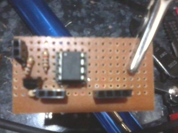
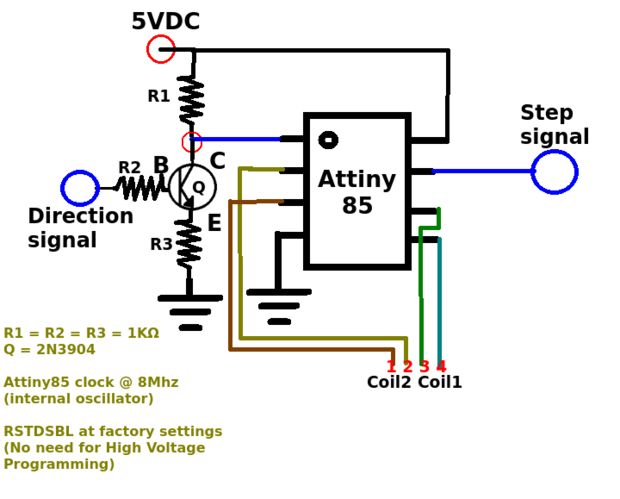
Step 4: The Circuit
And when it comes to CNCing, computers find it hard too. It is difficult even for computers, to control all the above combined with the needs of a CNC device: steady velocity, measured acceleration, simultaneous motion and taking a note of every rotor at any given time.
But when we face problems with multitasking we have the most elegant solution (when it comes to engineering):
Split the tasks to more than one worker. And that happened. The computer got rid of anything that has to do with voltages and combinations of wires. A simple interface was given to the computer so it could communicate with the motor. An interface that only contains 2 signals. A Step signal that every time it goes High (edge triggering) the motor has to move 1 “step” and a Direction signal that decides at which direction would be the step (ex: High for CW, Low for CCW).
So this is the Step/Dir interface.
Now a second device was needed to translate the Step/Dir signals to actual 4-wire signals, move the motor and generally do the hard work. This device is the Stepper Controller. And as of today, only one type of this device exists commercially: the hardware one. It uses H-bridges along with some kind of hardware logic, and other tricks ending up to quite complicated device. So it isn’t that cheap too… They can reach even 60 euros or more for multiple motors.
So, the first reaction when I got an idea about how to program Attinies was “Why hasn’t anyone made a software controller, by just coding the combinations in an Attiny85” (There have been some success with Attiny2313 by another Instructable and a sole attempt with Attiny85 that isn’t very satisfying)
Attiny85 is a microcontroller. It contains a processor, some RAM, some free space, to save and load things, and offers some of its processor’s register bits as IO pins.
Here lies the problem. Attiny85 has 8 pins at its DIP package, 2 of them being power supply. And you may assume that the rest are pure IO. That’s wrong. Well, almost, wrong… The 5 of the remaining pins are IO and there is that 1 pin that is used for RESET (if you bring it Low the microcontroller will restart). To make things worse, RESET pin is connected to some register, so it has the potential to BE an IO pin. There is also a fuse inside the microcontroller that decides if this pin is used for RESET or IO. BUT if you change the fuse (the famous RSTDSBL) to use the pin as IO, the microcontroller can’t be reset again and, on top of it, it can’t be reprogrammed.
Now, back to the stepper controller device. It needs 2 pins, to read the incoming Step and Dir signals, and 4 to connect the stepper motor wires (or the base of some transistors to amplify the power delivered to the motor) and do the actual voltage combinations. So a controller needs (*at least*) 6 pins.
You see it, don’t you? The way god created things has made our little Attiny85 to be incapable of being used as a stepper controller properly. Until Now…
Step 4: The Circuit
For more detail: Attiny85 As a Step/Dir Stepper Motor Controller
- Why are commercial stepper controllers often expensive?
Commercial hardware controllers use H-bridges and complex logic, costing 60 euros or more for multiple motors. - What is the main advantage of steppers over DC motors?
Steppers offer precision by moving the rotor a specific amount of degrees for every voltage combination applied, allowing position tracking without feedback. - How does the Step/Dir interface simplify computer control?
The computer only sends two signals: a Step signal to trigger movement and a Direction signal to set rotation direction, offloading complex voltage combinations to the controller. - Why was the Attiny85 initially considered unsuitable for this project?
The Attiny85 has only 5 standard IO pins plus one reset pin, but a stepper controller requires at least 6 pins to read inputs and drive the motor wires. - How can the Attiny85 be made to work despite having insufficient pins?
The user can change the fuse setting (RSTDSBL) to disable the reset function and use the reset pin as a sixth IO pin. - What happens if you change the RSTDSBL fuse on the Attiny85?
The microcontroller cannot be reset again and cannot be reprogrammed after the fuse is changed. - What is the primary goal of this specific project?
To create a software-based stepper controller using an Attiny85 that is cheaper than existing hardware solutions.