Summary of AVR ATmega32 Mini Development Board – Interfacing LCD
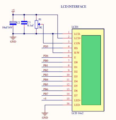
The AVR ATmega32 Mini Development Board interfaces with a 5V, 2×16 LCD module in 8-bit mode. The circuit uses PORTB for data lines (D0-D7), while PD5 and PD6 control the RS and E pins respectively. A potentiometer adjusts the contrast at pin 3 of the LCD. Upon power-up, the microcontroller initializes the display to show "Rhydo Technology" on the first line and "Cochin-17" on the second.
Parts used in the AVR ATmega32 Mini Development Board Interfacing Project:
- AVR ATmega32 Mini Development Board
- LCD module (2×16)
- Potentiometer
- Data lines (D0-D7)
- Control lines RS & E
AVR ATmega32 Mini Development Board is interfaced with a LCD module (2×16) operating at 5V. The voltage at the third pin of the LCD can be varied by potentiometer to adjust contrast. LCD can work either in 4 or 8 bit mode. Here, the circuit is designed to work in 8-bit mode. Control lines RS & E are connected to port pins PD5 & PD6 respectively and data lines (D0-D7) to PORTB in 8-bit mode. For reliable Performance, LCD has to be initialized with certain basic. On powering, microcontroller sends initialization commands to LCD. The sample code below gives the LCD display, in line1 “Rhydo Technology” and in line 2 “ Cochin-17 “.
Read More: AVR ATmega32 Mini Development Board – Interfacing LCD
- What voltage does the LCD module operate at?
The LCD module operates at 5V. - How is the contrast of the LCD adjusted?
The voltage at the third pin of the LCD is varied by a potentiometer to adjust contrast. - In which mode is this specific circuit designed to work?
The circuit is designed to work in 8-bit mode. - Which port pins are connected to the RS and E control lines?
RS is connected to PD5 and E is connected to PD6. - Where are the data lines connected in 8-bit mode?
The data lines D0 through D7 are connected to PORTB. - What happens when the microcontroller powers on?
The microcontroller sends initialization commands to the LCD for reliable performance. - What text appears on the first line of the display?
The text Rhydo Technology appears on line 1. - What text appears on the second line of the display?
The text Cochin-17 appears on line 2.