Summary of AVR Microcontroller. Pulse Width Modulation. Сontroller of DC Motor and LED Light Intensity.
This article details a project to control a DC motor's speed based on light intensity using an AVR microcontroller. The system employs Pulse Width Modulation (PWM) to regulate power, utilizing an LDR and the microcontroller's ADC for light sensing. A button allows users to toggle the motor's rotation direction and switch an LED tape. The core components include the ATmega328P microcontroller, an L298N dual H-bridge driver, and an LDR sensor.
Parts used in the Light Intensity Dependent DC Motor Controller:
- AVR Microcontroller (ATmega328P)
- Light Dependent Resistor (LDR)
- Dual H-Bridge Motor Driver Module (L298N)
- DC Motor
- LED Tape
- Button Switch
- Atmel Studio IDE
- ISP Programmer
Pulse Width Modulation (PWM) is a very common technique in telecommunication and power control. it is commonly used to control the power fed to an electrical device, whether it is a motor, an LED, speakers, etc. It is basically a modulationtechnique, in which the width of the carrier pulse is varied in accordance with the analog message signal.
We make simple electrical circuit to control rotational speed of the DC motor in light intensity dependent. We are going to use Light Dependent Resistor and AVR microcontroller features such as Analog to Digital Conversion to measure the light intensity. Also we are going to use Dual H-Bridge Motor Driver Module-L298N. It is typically used in controlling motors speed and direction, but can be used for other projects such as driving the brightness of certain lighting projects. Also, added a button to our circuit to toggle the direction of rotation of the engine.
Step 1: Description
Each and every body in this world has some inertia. The motor rotates whenever it is powered on. As soon as it is powered off, it will tend to stop. But it doesn’t stop immediately, it takes some time. But before it stops completely, it is powered on again! Thus it starts to move. But even now, it takes some time to reach its full speed. But before it happens, it is powered off, and so on. Thus, the overall effect of this action is that the motor rotates continuously, but at a lower speed.
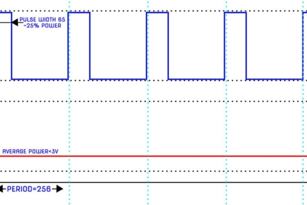
Pulse Width Modulation (PWM) is a comparatively recent power switching technique for providing intermediate amounts of electrical power between fully on and fully off levels. Usually, digital pulses have same on and off time period, but in some situations we need the digital pulse to have more/less on time/offtime. In PWM technique, we create digital pulses with unequal amount of on and off state to get required intermediate voltage values.
Duty cycle is defined by the percentage of high voltage duration in a complete digital pulse. It can be calculated by:
% of Duty cycle = T on /T (period time) x 100
Let us take a problem statement. We need to generate a 50 Hz PWM signal having 45% duty cycle.
Frequency = 50 Hz
Time period, T = T(on) + T(off) = 1/50 = 0.02 s = 20 ms
Duty Cycle = 45%
Thus, solving according to equation given above, we get
T(on) = 9 ms
T(off) = 11 ms
Step 2: AVR Timers – PWM Mode
For making PWM, AVR contains separate hardware! By using this, the CPU instructs the hardware to produce PWM of a particular duty cycle. The ATmega328 has 6 PWM outputs, 2 are located on timer/counter0 (8bit), 2 are located on timer/counter1 (16bit), and 2 is located on timer/counter2 (8bit). Timer/Counter0 is the simplest PWM device on the ATmega328. Timer/Counter0 is capable of running on 3 modes:
- Fast PWM
- Phase and Frequency Corrected PWM
- Phase Corrected PWM
each of these modes can be inverted or non-inverted.
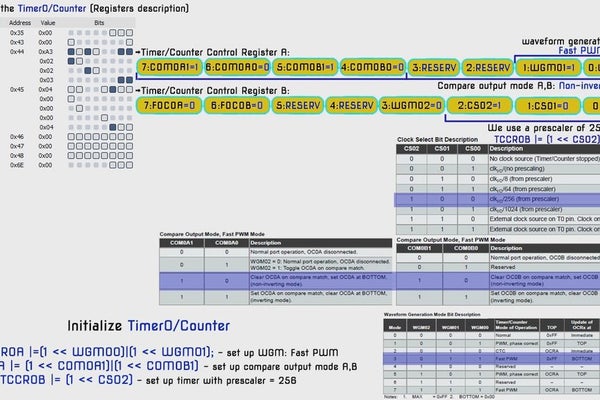
Initialize Timer0 in PWM mode:
TCCR0A |=(1 << WGM00)|(1 << WGM01) – set up WGM: Fast PWM
TCCR0A |= (1 << COM0A1)|(1 << COM0B1) – set up compare output mode A,B
TCCR0B |= (1 << CS02) – set up timer with prescaler = 256
Step 3: Light Intensity Measurement – ADC & LDR.
Light Dependent Resistor (LDR) is a transducer which changes its resistance when light falls on its surface changes.
LDRs are made from semiconductor materials to enable them to have their light sensitive properties. These LDRs or PHOTO RESISTORS work on the principle of “Photo Conductivity”. Now what this principle says is whenever light falls on the surface of the LDR (in this case) the conductance of the element increases or in other words the resistance of the LDR decreases when the light falls on the surface of the LDR. This property of the decrease in resistance for the LDR is achieved because it is a property of semiconductor material used on the surface. LDR are used most of times to detect presence of light or for measuring the intensity of light.
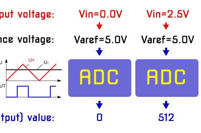
For transferring external continuous information (analog information) into a digital/computing system, we must convert them into integer (digital) values. This type of conversion is carried out by Analog to Digital Converter (ADC). The process of converting an analog value into digital value is known as Analog to Digital Conversion. In short, Analog signals are real world signals around us like sound and light.
Digital signals are analog equivalents in digital or numeric format which are well understood by digital systems like microcontrollers. ADC is one such hardware which measures analog signals and produces a digital equivalent of the same signal. AVR microcontrollers has inbuilt ADC facility to convert analog voltage into an integer. AVR convert it into 10-bit number of range 0 to 1023.
We use analog to digital convert of voltage level from divider circuit with LDR to measure the light intensity.
Initialize ADC:
TADCSRA |= (1<<ADEN) – Enable ADC
ADCSRA |= (1<<ADPS2)| (1<<ADPS1)| (1ADPS0) – set up ADC prescaler = 128
ADMUX = (1 << REFS0) – set up voltage referance = AVCC; – set up Input Channel = ADC0
Watch the video with a detailed description of the ADC AVR microcontroller: AVR Microcontroller. Light Intensity Measurement. ADC & LDR
Step 4: Controller DC Motor & Dual H-Bridge Motor Driver Module-L298N
We use DC motor drivers because microcontrollers are not capable of delivering current not more than 100 milliamps in general. The microcontrollers are smart but not strong; this module will add some muscles to microcontrollers to drive high power DC motors. It can control 2 DC motors simultaneously up to 2 amps each or one stepper motor. We can control the speed using PWM and also its rotational direction of the motors. Also, It used for driving the brightness of LED tape.
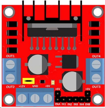
Pin description:
OUT1 and OUT2 port, which is for connecting DC motor. OUT3 and OUT4 for connecting LED tape.
ENA and ENB are enable pins: by connecting ENA to high(+5V) it enables the port OUT1 and OUT2.
If you connect the ENA pin to low(GND), it disables the OUT1 and OUT2. Similarly, for ENB and OUT3 and OUT4.
IN1 to IN4 are the input pins which will be connected to AVR.
If IN1-high(+5V), IN2-low(GND), the OUT1 turns high and OUT2 turns low, thus we can drive motor.
If IN3-high(+5V), IN4-low(GND), the OUT4 turns high and OUT3 turns low, thus LED tape light is on.
If you want to reverse the rotational direction of the motor just reverse IN1 and IN2 polarity, similarly for IN3 and IN4.
By applying PWM signal to ENA and ENB you can control the speed of the motors on two different output ports.
The board can accept from 7V to 12V nominally.
Jumpers:There are three jumper pins; Jumper 1: If you’re motor need more than 12V supply you have to disconnect the Jumper 1 and apply desired voltage (max 35V) at 12V terminal. Bring another 5V supply and input at 5V terminal. Yes, you have to input 5V if you need to apply more than 12V (when Jumper 1 is removed).
The 5V input is for proper functioning of the IC, since removing the jumper will disable the in-built 5V regulator and protect from higher input voltage from 12V terminal.
The 5V terminal acts as output if your supply is between 7V to 12V and acts as input
if you apply more than 12V and jumper is removed.
Jumper 2 and Jumper 3: If you remove these two jumpers you have to input the enable and disable signal from the microcontroller, most of the users prefer removing the two jumpers and applying the signal from microcontroller.
If you keep the two jumpers the OUT1 to OUT4 will be always enabled. Remember ENA jumper for OUT1 and OUT2. ENB jumper for OUT3 and OUT4.
Step 5: Writing Code for a Program in C. Uploading HEX File Into the Microcontroller Flash Memory
Writing and building the AVR microcontroller application in C Code using the Integrated Development Platform – Atmel Studio.
#ifndef F_CPU
#define F_CPU 16000000UL // telling controller crystal frequency (16 MHz AVR ATMega328P)
#endif#include  //header to enable data flow control over pins. Defines pins, ports, etc.
#include  //header to enable delay function in program#define BUTTON1 2 // button switch connected to port B pin 2
#define DEBOUNCE_TIME 25 // time to wait while "de-bouncing" button
#define LOCK_INPUT_TIME 300 // time to wait after a button press// Timer0, PWM  Initialization
void timer0_init()
{
	// set up timer OC0A,OC0B pin in toggle mode and CTC mode
	TCCR0A |= (1 << COM0A1)|(1 << COM0B1)|(1 << WGM00)|(1 << WGM01);
	// set up timer with prescaler = 256
	TCCR0B |= (1 << CS02);
	// initialize counter
	TCNT0 = 0;
	// initialize compare value
	OCR0A = 0;
}// ADC Initialization
void ADC_init()
{
	// Enable ADC, sampling freq=osc_freq/128 set prescaler to max value, 128
	ADCSRA |= (1<<ADEN) | (1<<ADPS2)| (1<<	ADPS1)| (1<<ADPS0);	ADMUX = (1<<REFS0); // Select Voltage Reference (AVCC)// Button switch status
unsigned char button_state()
{/* the button is pressed when BUTTON1 bit is clear */     if (!(PINB & (1<<BUTTON1))){_delay_ms(DEBOUNCE_TIME);if (!(PINB & (1<<BUTTON1))) return 1;}
return 0;}// Ports  Initialization
void port_init()
{
	DDRB =0b00011011;  //PB0-IN1, PB1-IN2,PB3-IN3, PB4-IN4, PB2 - BUTTON SWITCH DIRECT
	PORTB=0b00010110;	DDRD =0b01100000;  //PD5-ENB (OC0B), PD6-ENA (OC0A)
	PORTD=0b00000000;	DDRC =0b00000000; // PC0-ADC
	PORTC=0b00000000; // Set all pins of PORTC low which turns it off.
}// This function reads the value of the  analog to digital convert.
uint16_t get_LightLevel()
{
	_delay_ms(10); // Wait for some time for the channel to get selected
	ADCSRA |= (1<<ADSC); // Start the ADC conversion by setting ADSC bit.  Write 1 to ADSC	while(ADCSRA & (1<<ADSC)); // Wait for conversion to complete // ADSC becomes 0 again till then, run loop continuously
	_delay_ms(10);
	return(ADC); // Return the 10-bit result}// This function Re-maps a number from one range (0-1023) to another (0-100).
uint32_t map(uint32_t x, uint32_t in_min, uint32_t in_max, uint32_t out_min, uint32_t out_max)
{
	return (x - in_min) * (out_max - out_min) / (in_max - in_min) + out_min;
}int main(void)
{
	uint16_t i1=0;	port_init();
	timer0_init();
	ADC_init(); // initialization ADC	while (1)
	{
		i1=map(get_LightLevel(),0,1023,0,100);		OCR0A=i1; // Set output compare register channel A
		OCR0B=100-i1; // Set output compare register channel B (inverted)		if (button_state()) // If the button is pressed, toggle the LED's state and delay for 300ms (#define LOCK_INPUT_TIME)
		{
			PORTB ^= (1<<0); // toggling the current state of the pin IN1.
			PORTB ^= (1<<1); // toggling the current state of the pin IN2. Reverse the rotational direction of the motor 			PORTB ^= (1<<3); // toggling the current state of the pin IN3.
			PORTB ^= (1<<4); // toggling the current state of the pin IN4. LED Tape is turn off/on.
			_delay_ms(LOCK_INPUT_TIME);
		}
	};
	return (0);
}
Programming is complete. Next, building and compiling project code into hex file.
Uploading HEX file into the microcontroller flash memory:
type in DOS prompt window the command:
avrdude –c [name of programmer] –p m328p –u –U flash:w:[name of your hex file]
In my case it is:
avrdude –c ISPProgv1 –p m328p –u –U flash:w:PWM.hex
This command writes hex file to the microcontroller’s memory. Watch the video with a detailed description of the microcontroller flash memory burning: Microcontroller flash memory burning…
Ok! Now, the microcontroller works in accordance with the instructions of our program. Let’s check it out!
Source: AVR Microcontroller. Pulse Width Modulation. Сontroller of DC Motor and LED Light Intensity.
- How does PWM control the speed of a DC motor?
PWM creates digital pulses with unequal on and off times to generate intermediate voltage levels, causing the motor to rotate continuously at a lower speed. - What is the function of the L298N module in this project?
The L298N acts as a muscle for the microcontroller, allowing it to drive high-power DC motors up to 2 amps each and control their speed and direction. - How is light intensity measured in this circuit?
An Analog to Digital Converter (ADC) within the AVR microcontroller converts the analog voltage from the LDR divider circuit into a 10-bit digital number ranging from 0 to 1023. - Can the L298N be used for lighting projects?
Yes, the L298N can be used for driving the brightness of certain lighting projects, such as LED tape, by controlling the output ports. - How do you reverse the rotational direction of the motor?
You reverse the polarity of the input pins IN1 and IN2 connected to the AVR microcontroller to change the motor's rotation direction. - What happens if the supply voltage exceeds 12V?
If the motor needs more than 12V, Jumper 1 must be disconnected, and an external 5V supply must be applied to the 5V terminal to power the IC regulator. - Why is debouncing time included in the code?
Debounce time is added to wait while the button switch stabilizes after being pressed, ensuring the microcontroller reads the correct state. - What command is used to upload the hex file to the microcontroller?
The avrdude command with specific parameters like -c ISPProgv1 and -p m328p is used to write the hex file to the microcontroller's flash memory.