Summary of AVR Twinkle Twinkle Using PWM Project
This project demonstrates how to make an AVR ATmega168 microcontroller play musical notes, such as "Twinkle-Twinkle Little Star," using its 16-bit PWM feature. By generating square waves and feeding them directly to a speaker or piezoelectric material, the system leverages the inherent low-pass filtering of these components to approximate sine waves for sound production. This approach avoids complex integrator circuits while applying Fourier theory principles to create audible melodies from digital signals.
Parts used in the AVR Twinkle Twinkle Using PWM Project:
- AVR ATmega168 microcontroller
- 16-bit PWM peripheral
- Speaker
- Piezoelectric material
Would be interesting if we could make our microcontroller to sing for us not just beeping or blinking; this project is all about using the powerful AVR ATmega168 16-bit PWM feature to produce accurate musical notes such as playing the child’s favorite Twinkle-Twinkle Little Star song or we could say beeping with style. The principal we learned here could be applied to other AVR microcontroller families that support 16-bit PWM.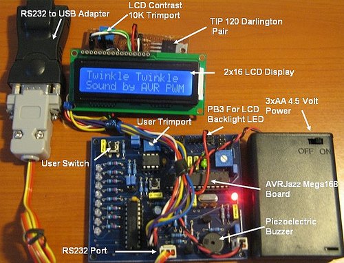
Basic natural sound we usually hear is formed by fast vibration; this vibration can be produced by many sources such as by string like guitar, piano, violin or by our vocal membrane when we sing or talk. All this sound produced the sound wave known as sine or sinusoid wave. By using the same principal we could produce sound electronically using oscillator circuit; this circuit basically is the amplifier with the input signal taken from the output or known as feedback. By amplifying this feedback signal over and over the amplifier become unstable and starts to oscillate; the output of this signal will be feed to the speaker and the speaker will vibrate according to the sound wave frequency.
This behavior can be observed when we talk on the microphone and if the microphone is close enough to the speaker suddenly we will hear the sound coming out from the speaker and usually we call it as the feedback sound.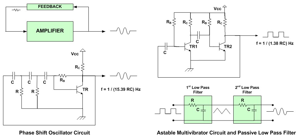
In the digital circuit we could create such vibration by using the same feedback principal; but the waveform generated by the digital circuit is a square waveform, therefore we have to change the waveform to the waveform normally produced by nature or the sine waveform. Normally we will use the integrator circuit or known as low pass filter to change the square waveform to the triangle waveform and another low pass filter to change this triangle waveform to the sine waveform.
The explanation of how it works required complex mathematical equations; but we could express it in practical terms that the square wave signal actually is a combination of the fundamental sine wave frequency plus all the odds sine wave harmonic frequencies at diminishing amplitude. This statement is known as a Fourier’s theory. For example if we have a square wave signal with frequency of 1 kHz, according to the Fourier’s theory we could represent this signal as a sum of all series of sine wave signals start from 1 kHz (the fundamental), 3 kHz (third harmonic), 5 kHz (fifth harmonic), 7 kHz (seventh harmonic), 9 kHz (ninth harmonic) and so on.
Therefore by passing the fundamental frequency and filtering all the harmonic frequencies using the low pass filter, we could get the fundamental sine wave signal. Another dirty method is to feed directly the square wave output to the speaker or piezoelectric material which works as the low pass filter; this is the method we used in this project. By using the sophisticated AVR PWM peripheral it’s easy for us to generate this square wave signal.
For more detail: AVR Twinkle Twinkle Using PWM Project
- What is the main goal of this project?
The goal is to use the AVR ATmega168 16-bit PWM feature to produce accurate musical notes like playing Twinkle-Twinkle Little Star. - How does the circuit produce sound electronically?
Sound is produced by creating vibration via an oscillator circuit where feedback makes the amplifier unstable to oscillate and vibrate a speaker. - What type of waveform does a digital circuit generate?
A digital circuit generates a square waveform rather than the natural sine waveform. - How can a square wave be converted to a sine wave?
Normally, an integrator or low pass filter changes a square wave to a triangle wave and then to a sine wave. - What method did this specific project use to get a sine wave?
The project fed the square wave output directly to a speaker or piezoelectric material which acts as a low pass filter. - Does this technique apply to other microcontrollers?
Yes, the principal learned here could be applied to other AVR microcontroller families that support 16-bit PWM. - What theory explains the composition of a square wave signal?
Fourier's theory states that a square wave is a sum of the fundamental sine wave frequency plus all odd sine wave harmonic frequencies. - Why is the direct feed method considered a dirty method?
It is called a dirty method because it skips the sophisticated integrator circuit steps usually required to shape the waveform.