Summary of AVR USB Devices and Programming
This article documents designing, fabricating, and programming a USB-capable AVR microcontroller board (ATmega16U2/32U2). It covers choosing hardware USB vs. software emulation, circuit design choices (48 MHz clock via 8/16 MHz crystal, load capacitance, impedance resistors), PCB layout/milling tips, soldering techniques, DFU bootloader behavior, and using dfu-programmer to erase, flash, and run firmware (example blink project with Makefile). The board successfully enumerates as ATmega16u2 DFU and is programmed over USB without an ISP.
Parts used in the USB AVR Device Project:
- ATmega32U2 (pin-compatible with ATmega16U2)
- 16 MHz quartz crystal (HC-49 SMD package)
- Capacitors for crystal (two 10 pF used as approximation for 22 pF)
- USB A connector (mounted on PCB)
- Impedance matching resistors for D+ and D- (two 49.9 Ohm stacked as approximation for 22 Ohm)
- Power LED
- RGB LED (connected to hardware PWM pins)
- Three switches
- PCB (milled board with adjusted TQFP32 pads)
- Solder, solder wick, masking tape (for assembly)
During this week’s lecture, we delved into a relatively less-explored subject: USB, a widely-used protocol enabling computers to interact with peripheral devices equipped with microcontrollers. Developing a USB device empowers any computer to establish communication without the need for the specialized software and hardware that have been our focus thus far. For the next two weeks, my goal is to grasp the essentials for designing circuitry compatible with USB and to develop the software required for computer-device interaction.
This is an epically long post about creating a USB device from scratch and programming it.
Hardware or Software USB?
Creating a USB device involves the task of programming a microcontroller capable of communicating with a computer using the USB protocol. In our previous coursework, we’ve been developing microcontroller code for various communication protocols. USB communication can also be achieved using the V-USB library, but this approach involves the microcontroller emulating USB functionality through software, which has some drawbacks, including slower performance and the microcontroller needing to allocate time for USB communication.
In contrast, microcontrollers equipped with hardware USB support delegate the necessary computations to dedicated circuitry. Within Atmel’s AVR line, devices like Mega and XMega with the U suffix offer hardware USB support. To write microcontroller code that interacts with the USB hardware, there are useful helper libraries like Atmel’s USB stack and LUFA. I’ll be focusing on exploring LUFA because it’s open source, well-documented, and offers numerous practical examples.
Circuit Design
In our classroom inventory, we possess a few devices featuring hardware USB support: the ATmega16U2 and the ATXMEGA16A4U. Given the current limited support for XMEGA AVRs in LUFA, I have chosen to utilize the ATmega chip.
Now, when it comes to using the ATMega16U2, there’s a lack of readily available USB device circuit examples for microcontrollers online. Even the datasheet is somewhat vague in terms of application circuit examples. After a thorough search, I was pleased to find that the Arduino Uno revision 3 employs an ATMega16U2 chip as a USB to serial converter for the actual ATmega328p being programmed. Its schematic proved to be a valuable reference for constructing a basic circuit.
From my research across various datasheets and other examples, I’ve identified several important considerations for designing these circuits:
1. To achieve Full-speed (12 Mbit/s) USB, the microcontroller must be capable of generating a precise 48 MHz clock with a deviation of no more than 0.25%. Since resonators have a 0.5% tolerance, this means only quartz crystals are suitable, and they must evenly divide into this frequency for a phase-locked loop to generate the clock. For the ATMega16U2, this necessitates an 8MHz or 16MHz crystal – there are no substitutes.
2. Different quartz crystals at the same frequency are not interchangeable; they are specified with a fixed load capacitance that must be matched by the circuit for the specified accuracy. Significant deviations in capacitance can result in the crystal operating at a different frequency than intended.
3. Impedance matching resistors are required for the USB signaling pins to optimize signal quality. The datasheet provides information on these resistors, and I obtained further clarity by posting a question on Electronics StackExchange.
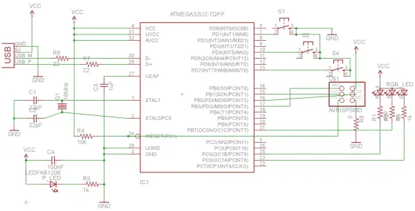
After completing my due diligence in circuit engineering, I was prepared to create the schematic. Because I used some non-standard components, I found the Ladyada and Sparkfun Eagle libraries to be quite helpful. In the circuit depicted below, I’ve incorporated a 16MHz crystal in an HC-49 surface mount package, an ATmega32U2 (pin-compatible with the ATmega16U2), and a USB A connector directly on the PCB.
The Eagle libraries also include supply components, which simplify the process of establishing VCC and GND connections by allowing you to place parts instead of manually naming nets. I highly recommend this workflow. Additionally, take note of the impedance matching signaling resistors and the capacitors paired with the crystal; I borrowed their values from the Uno rev. 3 due to its similar configuration.
Furthermore, there’s an automatic power LED indicator that activates when the board is powered on, a valuable feature. The RGB LED in the circuit is linked to hardware PWM pins, enabling full color control by adjusting the corresponding PWM rates.
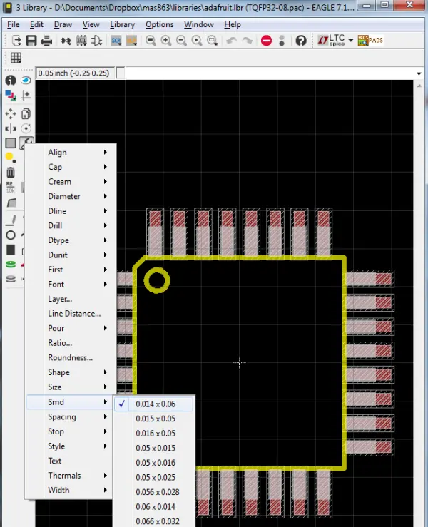
The mega16U2 is available in a TQFP32 package, which is similar in size to the mega328P. However, compared to the pins on the tiny44 and tiny45, these pins are much closer together and smaller. To create traces for them, you’ll either need to use a 10 mil end mill or modify the pads to provide more space. Considering the overall challenges associated with 10 mil end mills, I chose to adjust the pad sizes to enable milling the board with the standard 1/64″ end mill. It’s worth noting that this modification makes the pads narrower than the pins, which can make soldering a bit more challenging.
To modify the pad size, you can simply open the library in Eagle and use the following menu. In this case, I altered the pads of the TQFP32 package from 0.16 x 0.05 to 0.14 x 0.06 – making them slightly thinner but longer. When routing the board, I used 0.14″ traces to connect to all the pads and widened them to 0.16″ traces as soon as they extended beyond the vicinity of the microcontroller.
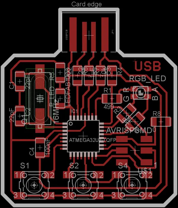
Here is the board, fully arranged as intended. My initial design was quite ambitious, featuring a multitude of LEDs and switches. However, I soon realized that I had taken on more than I could effectively manage, particularly when it came to fitting everything on a single-sided board. Consequently, I streamlined the design by eliminating numerous extra components and settling for three switches and a single RGB LED.
After investing a substantial amount of time in routing, I arrived at this concise and balanced design, incorporating the integrated USB connector. It’s unfortunate that the mega16U2 lacks any ADC hardware, as I would have gladly integrated multiple sensors to obtain data to be later accessed via USB.
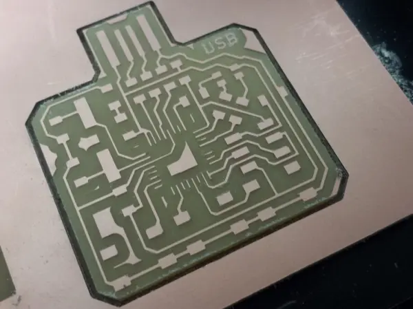
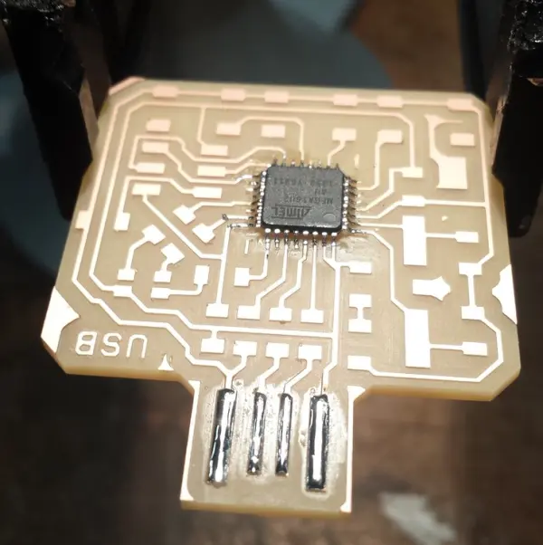
The outcome of milling the board is now visible. It’s worth noting that there are a few traces peeling off in the central area of the board, which is not the ideal outcome. Even though this board was exported at 1200 DPI, it wasn’t sufficient for capturing the extremely fine details in the middle section. Ideally, the microcontroller pads and traces should only be slightly narrower than usual, but in some areas, they appear to be significantly narrower. If I were to repeat this process, I would opt for an even higher resolution when exporting.
Nevertheless, no critical damage has occurred, and it is hopeful that soldering will be effective in securing everything in place.
While I deviated from the standard 4 offset paths and instead employed 6, there are still copper traces present along the board’s perimeter. This became an issue near the USB connector, as we aimed to prevent inadvertent short-circuits between pins. To address this concern, I carefully removed these undesired copper segments using an X-acto knife.
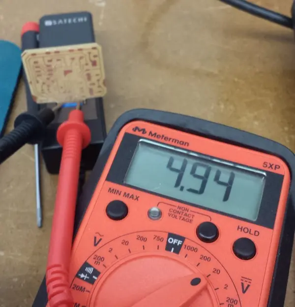
Subsequently, I conducted a test by inserting the board into a USB socket and measuring the pin voltages, primarily to verify the functionality of the connector:
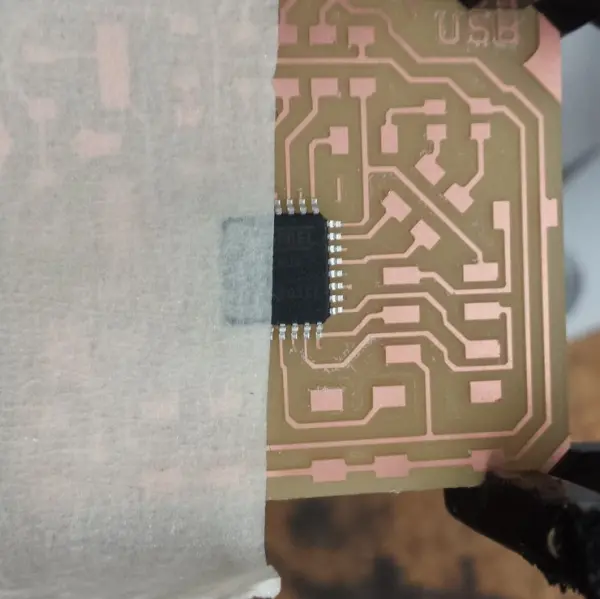
Soldering extremely small components onto a circuit board can be an exceptionally challenging task. One of the primary difficulties lies in the initial placement of the integrated circuit (IC). I was reluctant to use an initial solder joint for positioning the chip because this approach carried the risk of damaging the fragile traces, and attempting to position it with tweezers was quite cumbersome. At this point, Nate Melenbrink came up with an ingenious suggestion: applying tape over half of the chip to aid in its placement. Surprisingly, this method proved to be highly effective. The tape’s length creates a kind of “arm,” making it much easier to fine-tune the positioning, and it can be pressed down to secure the component in place. Masking tape is particularly suitable for this purpose and doesn’t leave any residue behind.
The individual traces on this chip are too minuscule for individual soldering. Instead, solder them all together in a row, and employ a wick to absorb any surplus solder.
Simultaneously, I’ve applied a layer of solder to the USB connection pins. This action serves a dual purpose. Firstly, it acts as a shield to safeguard the copper traces against oxidation, preventing the pins from developing a film that hinders electrical connectivity. Secondly, it enhances the thickness of the contacts, ensuring a snug fit when they interface with the USB socket.
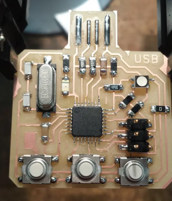
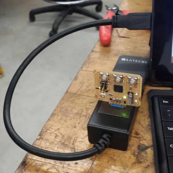
It’s important to mention that the schematic originally called for 22pF capacitors to be placed between the crystal terminals and ground, along with 22 Ohm resistors on the signaling pins. Since we lacked these specific components in our inventory, I employed an approximation by soldering two 10pF capacitors on top of each other for the crystal, and two 49.9 Ohm resistors stacked together for the signaling pins. The completed board is displayed below:
Upon plugging it into the USB port, the power LED illuminates, and there are no indications of smoke or heat. This is an encouraging indication.
A strong indicator of successful operation is the prompt appearance of the board in the Windows Device Manager, where it is recognized as a USB device labeled “ATmega16u2 DFU.”
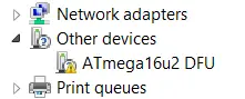
Please take note that the microcontroller has not been programmed yet. However, this is due to the fact that all AVR chips equipped with hardware USB are equipped with a DFU (Device Firmware Updater) bootloader. This bootloader enables the chips to be programmed directly via the USB port, eliminating the need for an ISP or any other external programmer. The DFU bootloader appears as a USB device, making it recognizable by a computer.
As a result, the microcontroller can establish communication with the computer, and we are now ideally positioned to proceed with programming the board.
Programming via DFU
The DFU bootloader, or bootloaders in general, offer a convenient means of uploading code without the requirement of an ISP (In-System Programmer). Atmel provides the FLIP program for interacting with DFU chips, although it appears that it hasn’t seen updates in quite some time. An open-source alternative for this purpose is dfu-programmer, akin to avrdude but tailored for uploading code via DFU.
It’s important to bear in mind that the DFU protocol does not allow for changes to the fuses; only the flash and EEPROM can be modified in this manner. Fortunately, AVR chips with hardware USB come pre-programmed with fuses set to use an external crystal oscillator as the clock source, provided the crystal operates at either 8 MHz or 16 MHz with appropriately matched capacitors. This configuration works immediately.
Should you wish to alter the fuses, an ISP or another programmer is necessary. You can make use of the website http://www.engbedded.com/fusecalc/ to determine fuse settings for AVR chips with which you may not be familiar.
It’s worth noting that the datasheet incorrectly states that the fuses are initially configured to use the internal 8 MHz RC oscillator with CKDIV8 set, resulting in a default system clock of 1 MHz. This information is incorrect, as the DFU bootloader would be unable to establish USB communication with the computer under such conditions. Further details can be found in this thread.
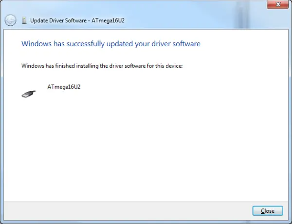
Installing dfu-programmer is a relatively straightforward process. On Windows, it also includes a libusb-win32 driver that enables communication with the DFU bootloader over USB. You can install this driver through the Device Manager.
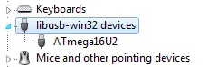
The board then shows up as ATmega16U2 under libusb-win32 devices when the bootloader is running.
Before proceeding with USB programming, it’s essential to consult the dfu-programmer documentation. One critical point to keep in mind is that you must perform a complete chip erase before executing any other commands. The subsequent command accomplishes this task and also clears the lock bits in flash memory:
dfu-programmer atmega16u2 erase –force
Erasing flash… Success
Checking memory from 0x0 to 0x2FFF… Empty.
Now, it’s time to program the board. As is commonly advised, I’ll begin with a straightforward task: making the LEDs blink. Below is the Makefile I’ll be using for programming and erasing the board via DFU:
PROJECT=blink
SOURCES=$(PROJECT).c

MMCU=atmega16u2
DFU_TARGET=$(MMCU)

F_CPU=16000000

CFLAGS=-mmcu=$(MMCU) -Wall -Os -DF_CPU=$(F_CPU)

$(PROJECT).c.hex: $(PROJECT).out
    avr-objcopy -O ihex $(PROJECT).out $(PROJECT).c.hex;\
    avr-size --mcu=$(MMCU) --format=avr $(PROJECT).out

$(PROJECT).out: $(SOURCES)
    avr-gcc $(CFLAGS) -I./ -o $(PROJECT).out $(SOURCES)

program-dfu: $(PROJECT).c.hex
    dfu-programmer $(DFU_TARGET) flash $(PROJECT).c.hex

erase-dfu:
    dfu-programmer $(DFU_TARGET) erase

clean:
    rm $(PROJECT).c.hex $(PROJECT).out
Please be aware that the compilation toolchain remains largely consistent, with the exception that the hex file is loaded using dfu-programmer rather than avrdude. Following the initial programming, it is necessary to erase the flash before proceeding with subsequent programming. This erasure is achieved through the “erase-dfu” target. Assuming everything is functioning as expected, the programming process is quite straightforward:
> make program-dfu
dfu-programmer atmega16u2 flash blink.c.hex
Checking memory from 0x0 to 0xFF...  Empty.
0%                            100%  Programming 0x100 bytes...
[>>>>>>>>>>>>>>>>>>>>>>>>>>>>>>>>]  Success
0%                            100%  Reading 0x3000 bytes...
[>>>>>>>>>>>>>>>>>>>>>>>>>>>>>>>>]  Success
Validating...  Success
0x100 bytes written into 0x3000 bytes memory (2.08%).
At this juncture, it might appear that the programming has been successful, yet the LED isn’t blinking, and the device continues to be recognized with the DFU driver. However, there’s no need for alarm in this situation. This happens because the bootloader is still in control, and the switch to the program code hasn’t occurred yet. To initiate the execution of the uploaded program, you can either use the command “dfu-programmer (target) reset” or simply unplug and reconnect the board.
Consequently, we now have a convenient method to program a board directly via USB, without the need for any additional tools. Essentially, this process is akin to what Arduino accomplishes, albeit without the user-friendly graphical interface and associated tools. In the image below, you can see the LED blinking after programming it directly from a USB port on my desktop. Voilà, no need for an ISP!
Source: AVR USB Devices and Programming
- Can I use a resonator instead of a quartz crystal for Full-speed USB?
No. The article states resonators have 0.5% tolerance and are unsuitable; a quartz crystal (8 MHz or 16 MHz) is required for the ATMega16U2 to meet the 48 MHz PLL tolerance. - Why must crystal load capacitance match the crystal specifications?
Because different crystals have fixed load capacitance and mismatched capacitance can shift the operating frequency away from the intended value. - Are impedance matching resistors needed on USB signaling pins?
Yes. The article notes that impedance matching resistors are required for the USB signaling pins to optimize signal quality and references values borrowed from the Arduino Uno rev. 3. - Can I program the ATmega16U2 over USB without an ISP?
Yes. The chip ships with a DFU bootloader allowing programming via USB using tools like dfu-programmer or FLIP, removing the need for an ISP. - Does DFU allow changing fuse settings?
No. The DFU protocol only allows modifying flash and EEPROM; fuse changes require an ISP or other programmer. - What should I do before programming with dfu-programmer?
The article instructs to perform a complete chip erase first using dfu-programmer atmega16u2 erase --force to clear flash and lock bits. - How do I run the uploaded program after flashing via DFU?
Either issue dfu-programmer target reset or unplug and reconnect the board to exit the bootloader and start the program. - What workaround helped place the TQFP32 chip for soldering?
Masking tape applied over half the chip was used as an arm to position and press the component into place. - Can I use stacked components if exact parts are unavailable?
Yes. The author stacked two 10 pF capacitors to approximate 22 pF and stacked two 49.9 Ohm resistors to approximate 22 Ohm when exact parts were not available. - What issue occurred when exporting PCB for milling and how to avoid it?
Some traces peeled due to insufficient export resolution; the author suggests exporting at higher resolution to better capture fine details.