For those of you who remember the eighties, this will no doubt bring back fond memories when every piece of audio equipment in the known universe was at the time equipped with a plethora of LEDs.
More specifically the ubiquitous Graphic Equaliser or ‘Graphic EQ’.
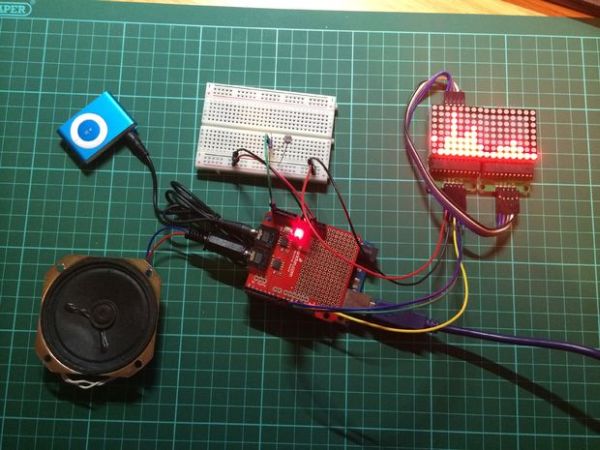
This Instructable is centred around the MSGEQ7 to create a simple 2 Channel Graphic EQ (actually a simple spectrum analyser) and documents my first, poor attempt at using the Arduino Uno R3, the Arduino development environment and coding in ‘C’ for well over a decade.
To make the above the circuit you require no tools, a basic knowledge of electronics and the following parts/libraries;
- 3 off prototyping wires male/male connectors in the picture above (Red, Black and Green) to connect to the Light Dependant Resistor (LDR).
- 5 off prototyping wires male/female connectors again in the picture above (Red, Black, Blue, Green and Yellow) to connect to the 8×8 Led Matrix.
- 2 off 8×8 Led Matrices. From leading-star on Amazon. £1.90 (This was the price at the time of purchase, but I have noticed they are slightly more expensive, priced at £2.09 at the time of writing this Instructable).
- 1 off LDR. From Farnell.
- 1 off 22K Resistor. From Farnell
- 1 off Arduino Uno. From Proto-Pic £18.65. www.proto-pic.co.uk/arduino-uno/
- 1 off Spectrum Shield. From Proto-Pic. £22.25. www.proto-pic.co.uk/spectrum-shield/
- The Arduino LedControl library in Git Hub.https://github.com/wayoda/LedControl/releases
The circuit allows for the display of left and right audio channels. Seven of the columns of each 8×8 display represent a scaled analogue of the following frequency components present in the audio signal path at any transient in time.
16kHz, 6.26kHz, 2.5kHz, 1kHz, 400Hz, 160Hz and 63Hz
The data sheet for the MSGEQ7 can be found here; https://www.sparkfun.com/datasheets/Components/General/MSGEQ7.pdf
The last column represents a rolling average value of all the frequency components.
Audio is supplied to the Spectrum Shield via either of the on board 3.5mm Jack sockets, the other socket is used to route this audio to a speaker.
The circuit diagram for the Spectrum Shield can be found here; http://dlnmh9ip6v2uc.cloudfront.net/datasheets/Dev/Arduino/Shields/SpectrumShield-v14.pdf
The LDR is used to programmatically dim the 8×8 LED Matrix displays if the ambient light level drops to allow better contrast for the viewer.
Step 1: Detailed design
Step 2: Tidy Up
Now the software was working I tidied up the circuit and committed to a veroboard design which fitted neatly on top of the stacked Arduino Uno and Spectrum Shield pair.
Finally I modified the pins on the 8×8 LED Matrices such that they were perpendicular to the circuit board and would be a push fit into the 0.1″ pitch headers on the veroboard.
Detailed pictures above.
For more detail: Back to the 1980s with the Graphic EQ