Summary of Basic Servo Motor Controlling with Microchip PIC Microcontroller
This tutorial explains how to control a Parallax continuous servo motor using a PIC 16F690 microcontroller and LDR light sensor. It details the PWM signal requirements, compares three frequency generation methods, and implements a light-seeking robot algorithm where the servo adjusts position based on ambient light levels detected by the photoresistor.
Parts used in the Light Seeking Robot:
- Parallax Continues Servo
- PIC 16F690 Microcontroller
- LDR (Light Dependent Resistor)
The servo motor is widely used in model hobbyist such as airplane R/C model for moving the rudder, ailerons, elevators and acceleration control or in the car R/C model for steering and acceleration control. In this tutorial we will learn how to control the servo motor as well as the simple close loop control algorithm for this servo motor.
The servo motor basically is a high quality geared DC motor equipped with electronic circuit for controlling the DC motor rotation direction and position. Currently there are two types of servo motor available on the market, the first one is called standard servo and the other one is called continues servo; standard servo can rotate to maximum (clockwise or counterclockwise) of 120 to 180 degrees while continues servo can rotate up to 360 degrees in both direction.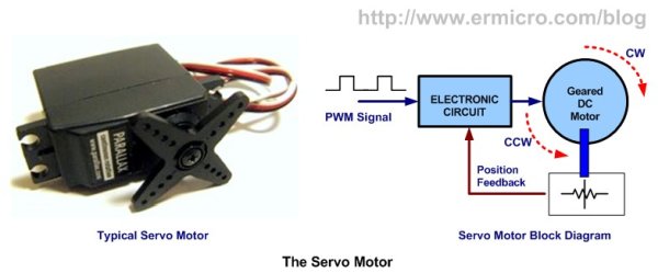
The Servo Motor
The servo motor use PWM signal for controlling the DC motor; unlike normal PWM usually used in ordinary DC motor; this PWM signal is not use for controlling the rotation speed, instead it is use for controlling the motor direction or position. Most servo motor will work well on 50 Hz of PWM frequency; this mean the PWM signal should have a period of 20ms. The electronic circuit inside the servo motor will response to the PWM signal width; the 0.7ms to 1ms PWM width will make the servo motor to turn clockwise (CW), the 1.7ms to 2ms PWM width will make the servo motor to turn counterclockwise (CCW). For the standard servo the 1.5ms PWM width will turn the servo motor to its center.
The exact PWM width is depend on the servo motor types and brands; on this tutorial we will use the Parallax Continues Servo which using 1ms and 2ms respectively. The Parallax servo motor consists of three wires colored with White, Red and Black. The Red and Black wires go to the Vcc and Gnd, while the White wire is use to feed the PWM signal from the PIC 16F690 microcontroller I/O port.
Driving the servo motor using PIC 16F690 microcontroller might be simple as you thing at the first time; we just use the PIC PWM peripheral to do the job (you could learn of how to use the PIC PWM peripheral on the article H-Bridge Microchip PIC Microcontroller PWM Motor Controller posted on this blog), but looking at the PIC 16F690 datasheet with the 8 Mhz of internal frequency clock (use in this tutorial) and using maximum prescaler of 16 (TIMER2) the minimum PWM frequency we could achieve can be calculated using this formula:
PWM period = [( PR2 + 1) ] x 4 x Tosc x (TMR2 prescaler value) second
Using maximum PR2 register value of 0xFF (255 decimal), we will get this result:
PWM period = (255 + 1) x 4 x (1 / 8000000) x 16= 0.002048 second
PWM frequency = 1 / PWM period = 1 / 0.002048 = 488.28 Hz
The 488.28 Hz frequency is still too high from the servo motor working frequency of 50Hz; therefore this leads us to these three methods bellow:
- Keep using the PIC PWM peripheral and lower the operation frequency by setting the OSCCON register and PR2 register until it meets the servo motor frequency requirement. This approach will secrify the program execution speed as we will operate the PIC Microcontroller with the 500 khz clock speed, so we simply not choose it.
- Secondly, we create our own PWM function to mimic the PWM signal as follow: turn on the PORT, make some 2 ms delay, turn off the PORT, and make some 18 ms delay and so forth. This approach is what I called a dirty method which is not the efficient way to do it, so we just drop this method.
- The third approach is to use the PIC 16F690 microcontroller TIMER0 with the interrupt to actually generate the PWM signal as the TIMER0 have wider prescaler to choose comparing to the TIMER2, but unfortunately the PWM peripheral on the PIC 16F690 only work with TIMER2 not TIMER0. Therefore we will make this TIMER0 as our PWM base generator for driving the servo motor on this tutorial. The principal we learn here could be applied to the other type of PIC Microcontroller or AVR Microcontroller as well.
Instead of just demonstrating the servo motor to rotate clockwise and counterclockwise, I decide to make it more challenging and attractive by putting the LDR (light dependent resistor) as the light sensor to our servo motor and make this servo motor to behave as the light seeking machine; …hey this sound like we are touching the robotics field; …hmm yes isn’t it cool, as we know most of the embedded robotics hobbyist widely use the servo motor for robot’s arms, walkers robots, light seeking robot (know also as photovore robot) and many more.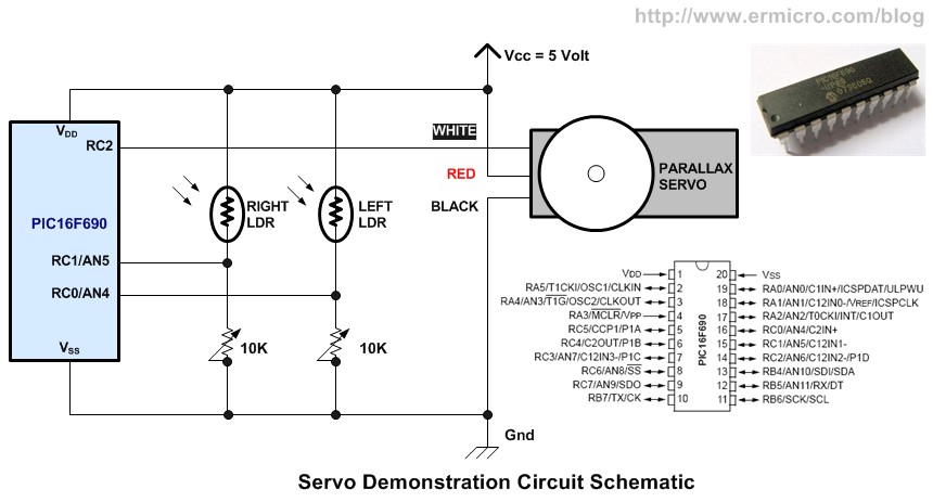
The LDR (Light Dependent Resistor)
By just looking at the name, is clear that this is the type of resistor that its resistance depends on the light intensity; it’s also called photoresistor, made from the Cadmium Sulfide (CdS) one of the semiconductor material. The LDR will response to light it received, the brightest the light the smaller its resistance and vise versa; on the complete darkness the LDR resistance will become very high (about 150K Ohm; for the LDRs I use in this tutorial)
For more detail: Basic Servo Motor Controlling with Microchip PIC Microcontroller
- How does the servo motor respond to PWM signals?
The electronic circuit inside responds to PWM width; 0.7ms to 1ms turns it clockwise, 1.7ms to 2ms turns it counterclockwise, and 1.5ms centers it. - What are the two types of servo motors available on the market?
The two types are standard servos that rotate up to 180 degrees and continuous servos that can rotate up to 360 degrees. - Why is the default PIC PWM frequency too high for this project?
The calculated minimum frequency is 488.28 Hz, which is much higher than the required 50 Hz operating frequency for most servos. - Which method was chosen to generate the correct PWM frequency?
The third approach using TIMER0 with interrupts was selected because TIMER2 lacks a wide enough prescaler range. - How does an LDR react to light intensity?
The resistance of the LDR decreases as the light gets brighter and becomes very high in complete darkness. - What is the purpose of the LDR in this specific project?
The LDR acts as a light sensor to make the servo motor behave as a light seeking machine or photovore robot. - What wires connect to the Vcc and Gnd on the Parallax servo?
The Red wire connects to Vcc and the Black wire connects to Gnd. - Can the principles learned here apply to other microcontrollers?
Yes, the principal of using TIMER0 to generate PWM can be applied to other types of PIC or AVR Microcontrollers.