Summary of BeatFlower With Digispark/ATtiny85 and WS2812b
This tutorial guides you in building the BeatFlower, a USB-powered, flower-shaped wall light that functions as a music visualizer. The project utilizes five WS2812b RGB LED rings daisy-chained to an ATtiny85 microcontroller on a Digispark board. Construction involves assembling these lights onto custom-cut acrylic plates using plastic screws and nuts, creating a translucent display powered via USB.
Parts used in the BeatFlower:
- 5x 12 bit RGB LED ring with WS2812b controller
- 1x ATtiny85 microcontroller on a Digispark USB Development Board
- 1x FT232R cable (FTDI for USB to serial)
- 2x Acrylic plate (black back and milky white front)
- Wire (thin, approx 0.3mm)
- Solder (regular type)
- Screws and nuts (plastic, 2mm diameter, M2 size)
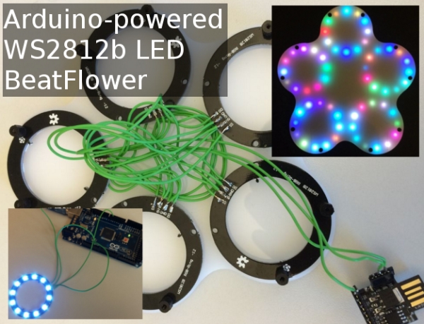
In this tutorial, I’m going to show you how to build a BeatFlower: A flower shaped, USB powered “wall light” that doubles as a color display for e.g. music on your computer.
I use the following components in this tutorial:
- 5x 12 bit RGB LED ring using the WS2812b controller
- 1x ATtiny85 microcontroller on a Digispark USB Development Board
- 1x FT232R cable (FTDI for USB to serial)
- 2x Acrylic plate
Additionally, I’m using the following consumables:
- Wire (thin, mine is around 0.3mm)
- Solder (the regular one)
- Screws and nuts (mine are plastic, 2mm diameter)
I used these tools for completing the project:
- Soldering iron (a normal one suffices)
- Wire cutter
During the process of making the BeatFlower, I also used an external service for cutting my acrylic plates. You might want to consider doing it yourself it you have access to a laser cutter; I will go into detail in the respective step.
Step 1: Testing the LED Rings
I got my LED rings through eBay for cheap from China (look for “ws2812b ring 12“). I got mine for around 2€ a pop (plus free shipping, yay). If you buy them from e.g. Adafruit they come in much more expensive, but of course you won’t have to wait four weeks for them to arrive.
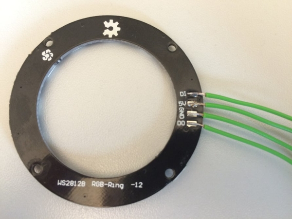
The controller used in these rings is a WS2812b. This neat little device has four pins and can be daisy-chained; you can control up to 1024 LEDs with one single line.
The four pins on it are:
- 5V: Your power supply. I tested 64 LEDs on full brightness with my regular USB power, worked just fine.
- GND: Ground of whatever power supply you use.
- DI: This is the “Data In” pin; you connect your microcontroller data pin to this.
- DO: This is the “Data Out” pin; if you daisy-chain these, this is what goes to the next element’s DI pin.
So for our tests for now we just need the first three pins. I soldered all of them anyway, as you can see on the picture. For testing purposes, I connected it to my ATmega2560 (see pictures). Connect 5V and GND to the respective pins on your ATmega (or equivalent) and use this code for testing it. I configured it to use pin 5 on the ATmega, so if you don’t change it in the code, connect your DI to your pin 5 as well.
This code uses the (GPLv3) NeoPixel library from Adafruit. I installed it via “Sketch/Include Library/Manage Libraries…” in my Arduino IDE. See the picture for the exact library to install; I used version 1.0.4. If your ring lights up like on the picture, you’re set. If not, check if you mixed up DI and DO, check all connections for loose cables, reflash the code on your microcontroller, and try again.
Step 2: Assembling the Lights, Adding an ATtiny85
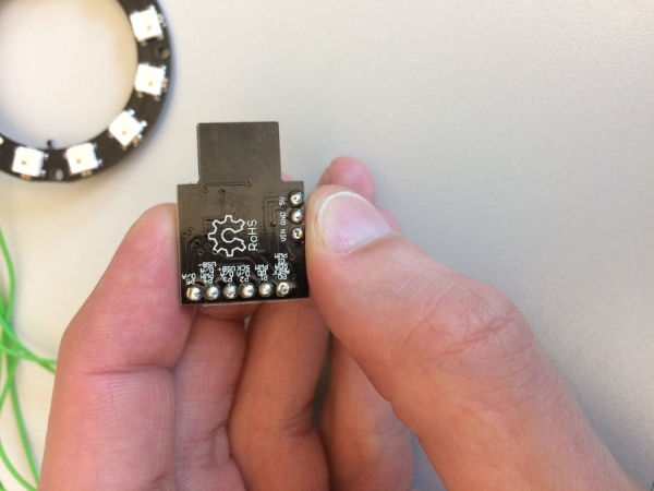
For convenience, I used a Digispark USB Development Board (driven by an ATtiny85) rather than directly using an ATtiny85. I got the Digispark for around 1.50€ from eBay (from China again, so waiting time applies). The reason to use this is that its flashable easily using USB, and it brings its own pins.
As you can see on the pictures, I daisy-chained the five LED rings. As mentioned before, the output (DO) of one ring goes to the DI of the next. The first DI is fed directly by the ATtiny85. An important thing to note here is that the physical pins on the controller and the software pins you define in your code don’t follow the same numbering. This article has a great schematic picture of it. So right now I’m using the software pin P0 (physical pin 5) as the output line. The Digispark actually has the software pins written onto its PCB to reduce confusion.
Besides DI and DO, you have to connect all 5V pins and all GND pins on the rings. Once you’ve done that, you’re set. If you want to test this, you have to change the NUM parameter in the test code from 12 to 60 (5×12) so that the NeoPixel library knows what to send. If everything lights up as expected, you’re good to go.
Step 3: Making the Frame for the Flower
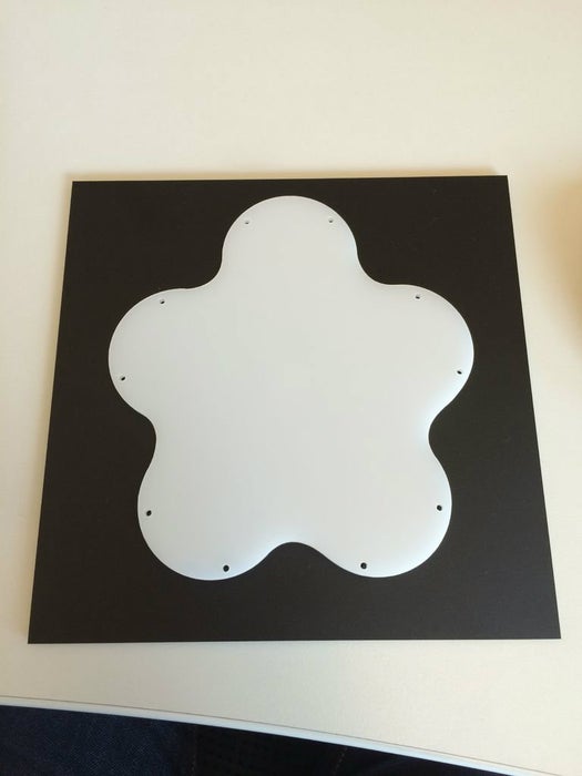
The flower frame itself consists of two parts: A black acrylic back plate, and a milky white, semi-translucent acrylic front plate. I let the awesome guys at FORMULOR* make these for me. The designs I sent them are available here; they are in exactly the format they accept. You’ll have to open them with Inkscape (or similar) to see the very fine hair lines that the laser cutter expects. They take about a week to ship and the results are awesome.
You can see my exact order on the picture. All in all I paid roundabout 17€ for the material, the cutting, and shipping. Not too bad.
Note that the holes on the schematics are 2mm in diameter. I chose this because the mounting holes on the LED rings are that size. This is a non-standard size (usually the smallest you can get is M3, which measures 3mm). To make this work, I ordered special plastic screws and nuts from smartshapes. Specifically, I got the screws as M2 in length 5mm and 8mm. Also, I bought the nuts there. You’ll need ten each, which luckily is exactly the amount they package. Plus shipping, this sums up to about 10€.
The back plate has an extra hole where the cables go out. You don’t see it through the semi-translucent front plate, but the lights are well visible through the front plate.
Step 4: Assembling the Lights Onto the Front Plate
To assemble the lights onto the front plate, simply push the longer 8mm screws through the holes, directly attach the LED rings onto them using the mounting holes, and put a nut on each.
Each LED ring has two mounting holes and all in all you’ll have to attach ten nuts. The best is to arrange them in a circular, clock-wise order, starting with the top one (if you look at the front plate’s shape, one sticks out; this is the top). This way, your design will be best compatible with the code I’m supplying for actually using it later on (in terms of numbering the rings when accessing them software-wise).
Also, the LED rings have four mounting holes. Use the outer two; this means, the cables go towards the center of the acrylic plate and are on the opposite side of the mounting holes you use. See the pictures for details.
It really is a bit of a squeeze with the cables I used, but they fit thanks to the distance nuts. You might consider making them shorter. Actually, after doing this, I realized that it might have been easier to first assemble the lights onto the front plate, then solder the cables. This way, the length of the cables would have been easier to estimate – plus, the LED rings are fixed and don’t slip away during soldering.
Source: BeatFlower With Digispark/ATtiny85 and WS2812b
- How can I test the LED rings before assembly?
You can test them by connecting 5V, GND, and DI pins to an ATmega2560 or equivalent and running code using the NeoPixel library from Adafruit. - What is the best way to connect multiple LED rings together?
You must daisy-chain the rings by connecting the Data Out (DO) pin of one ring to the Data In (DI) pin of the next. - Can I use standard M3 screws for mounting the rings?
No, the LED rings have non-standard 2mm holes, so you must use special M2 plastic screws and nuts instead of standard M3 hardware. - How do I ensure the software recognizes all LEDs correctly?
You must change the NUM parameter in your test code from 12 to 60 to account for the total number of LEDs across the five rings. - Does the physical pin numbering match the software pin definitions?
No, the physical pins on the controller do not follow the same numbering as the software pins defined in your code. - What tool is required to cut the acrylic plates for the frame?
An external laser cutter service is recommended to cut the acrylic plates according to the provided Inkscape designs. - Which side of the acrylic plate should the cables exit?
The back plate has an extra hole where the cables go out, which remains hidden behind the semi-translucent front plate. - Is it better to solder cables before or after attaching the rings to the plate?
The author suggests it might be easier to first assemble the lights onto the front plate, then solder the cables to estimate length and prevent slipping.