This project will use the Microchip AC164160 AVR-IoT WG Evaluation Board to build an Internet of Things (IoT) development environment and application. The board is designed for prototyping IoT solutions that securely connect sensors to the cloud. Specifically, we will configure the AVR-IoT WG board and Google Cloud to read hardware sensors and transmit real-time data securely to the cloud.

The board contains a cryptographic coprocessor that stores and protects the private key used to authenticate with Google Cloud. Once sensor readings are sent, cloud computing resources can store, process and analyze the data.
As we set up the environment and application, instructions will be provided to modify and rebuild the software to customize it. Going through this process establishes a foundation for prototyping other secure IoT applications. The end goal is an IoT solution that senses real-world data and transmits it securely to the cloud for storage and analysis.
Project Materials and Resources
The project bill of materials (BOM) outlines the necessary components. Supplementary hardware and software tools are also specified.
Project BOM
- Microchip AC164160 AVR-IoT WG Evaluation Board
- Type-A to Micro-B Universal Serial Bus (USB) cable
Hardware
The following wireless networking equipment and computer hardware are required:
11 b/g/n Wi-Fi access point with DHCP server capabilities for device IP addressing and Internet access. The access point should not have any firewalls or proxies blocking outbound traffic.
A personal computer running the Microsoft Windows operating system.
Accounts and Software
- Web browser for accessing software download sites and the Google Cloud Platform
- Atmel Studio 7
- Atmel START tool for selecting and configuring embedded software components
- Login account on the Google Cloud Platform
- Gcloud command-line tool
- Python®
- Serial terminal program, such as Tera Term
- Wi-Fi access point connection details, including a service set identifier (SSID) and security credentials
Project Technology Overview
AC164160 AVR-IoT WG Evaluation Board
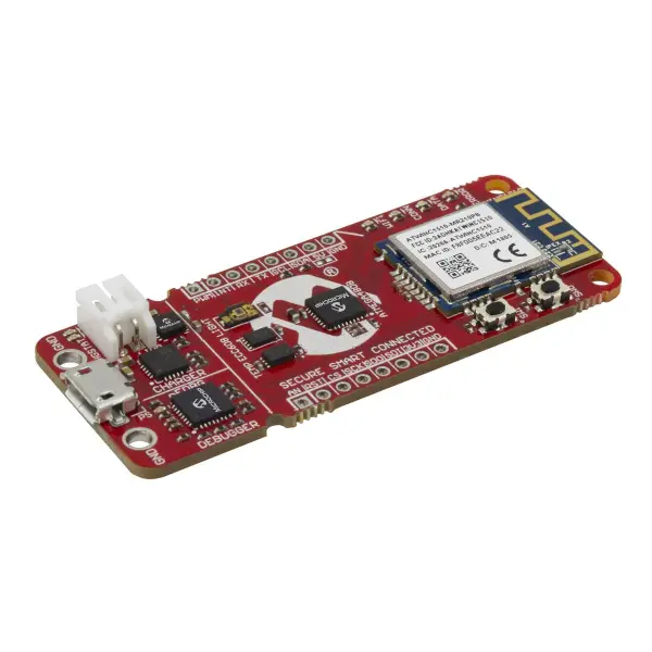
The central component for this project is the Microchip AC164160 AVR-IoT WG development board (Figure 1). It features the ATmega4808 microcontroller and ATECC608A cryptographic coprocessor to prototype low-power IoT applications with secure cloud connectivity and hardware-based security services.
Specifically, the board allows developers to test designs that connect sensors to cloud computing services over the Internet while authenticating, encrypting data for confidentiality and verifying integrity. It evaluates the full capabilities of the ATmega4808 and ATECC608A for securely integrating sensors and communicating over Wi-Fi.
More detailed technical specifications on the board’s components and features can be found via the provided link.
The board offers several important features that make it well-suited for prototyping secure IoT designs:
ATmega4808 microcontroller with 48KB flash and 6KB RAM
ATECC608A cryptographic coprocessor with protected storage for up to 16 keys, certificates, or sensitive data
Wi-Fi module supporting 802.11 b/g/n standards
Digital temperature and light sensors
Li-Po battery charger
Two push-buttons and four LED indicators
USB connector
mikroBUS expansion connector
On-board Nano Embedded Debugger (nEDBG)/programmer, serial port, and mass storage interface
The board connects via USB cable to a PC, supporting programming, debugging, drag-and-drop programming and serial communication from integrated development environments like Atmel Studio 7 and MPLAB X IDE for Windows, Mac and Linux.
The mikroBUS expansion connector allows interfacing with over 450 sensors and actuators from Mikroe’s Click boards portfolio, expanding the board’s functionality.
ATECC608A Cryptographic Coprocessor
The ATECC608A is a secure cryptographic coprocessor that combines internally stored keys with hardware acceleration for various authentication and encryption protocols. It features EEPROM storage that can securely hold up to 16 keys, certificates, or sensitive data with configurable access controls preventing changes. Private keys can be randomly generated and stored internally, ensuring they remain undiscoverable outside the device. Each chip has a guaranteed unique 72-bit serial number and utilizes hardware cryptographic operations for much faster performance over software alternatives. More details about this chip are available via the provided link.
In this project, the private key stored in the ATECC608A will authenticate the AVR-IoT board with Google Cloud IoT. This process eliminates any need to handle or configure a private key in software or other data. Each AVR-IoT board features a unique ATECC608A with its associated public and private key pair.
Atmel Studio 7
Microcontroller firmware is typically developed and tested using an integrated development environment (IDE) on a personal computer. The IDE provides editing, compiling, linking, debugging tools and the ability to transfer binary program files to a microcontroller.
The AVR-IoT WG board supports programming through multiple IDE options from Microchip. For this project, we will use the free Atmel Studio 7 IDE which runs on Windows. It supports Microchip’s full range of AVR and SAM microcontrollers and is available from their website.
Atmel Studio 7 is compatible with the nEDBG debugger built into the AVR-IoT WG board. This debugging interface allows compiled programs to be downloaded onto the board for execution while enabling debugging features like breakpoints and memory inspection.
Atmel START
Microchip provides the free Atmel START tool, available on their website, to help simplify project creation. It contains example projects and libraries that can be used to generate new source code.
The goal of Atmel START is to quickly set up projects containing the necessary functions and libraries to interface the AVR-IoT WG board with Google Cloud IoT over the internet. The included libraries interact with the ATECC608A crypto chip, Wi-Fi module, sensors and LEDs.
They also implement key communication and security protocols used by Google Cloud, such as Transport Layer Security (TLS), Message Queue Telemetry Transport (MQTT), and JavaScript Object Notation [JSON] Web Tokens (JWT). This streamlines connecting the board to cloud services through protocols like TLS, while sending and receiving sensor data via MQTT with authentication from JWT.
Google Cloud Platform and Google IoT Core
Google Cloud Platform is a suite of computing resources and tools hosted within Google’s global data centers. The platform offers a diverse set of pay-as-you-go services that can serve as useful building blocks for developing many types of applications. Some cloud services included are computing, storage, database management, networking, monitoring, containerization, mapping, data analytics, pub/sub messaging, machine learning, and IoT. Specifically, we will leverage Google Cloud IoT Core to integrate our development board with the broader Google Cloud environment.
Wi-Fi Access Point
The AC164160 AVR-IoT WG board includes an onboard Wi-Fi module capable of connecting to the internet via a Wi-Fi access point. The access point must support the 802.11 b/g/n wireless standards and provide a DHCP-assigned IP address to the Wi-Fi module. Additionally, the access point should permit outbound internet traffic without any blocking imposed by proxies or firewalls.
gcloud
Google Cloud SDK provides the gcloud command-line interface for managing Google Cloud resources directly from a PC’s terminal. As detailed further in the linked reference, gcloud allows interaction with Cloud services through textual commands. Specifically, we will utilize gcloud to view sensor data streaming in real-time to Google Cloud IoT, once our board is connected and transmitting measurements to the cloud platform.
The Setup (Hardware)
When preparing the hardware, it is important to exercise caution, as electronic components can be easily damaged by static electricity. Please take care when handling any devices or boards to avoid potential issues from static discharge.
PC
Power up your PC and allow it to boot up.
Wi-Fi Access Point
Before proceeding, ensure your Wi-Fi access point has an active internet connection and is functioning as a DHCP server to assign IP addresses. You will need the access point’s SSID, security type (e.g. WPA2), and credentials, as they will later be used when configuring the wireless settings of the development board.
AC164160 AVR-IoT WG Evaluation Board
Remove the board from its packaging and place it on a stable work surface. Using the included USB cable, connect the Micro-B end to the board’s port. Connect the other end to your PC. Once connected, the board will power on and LEDs should illuminate.
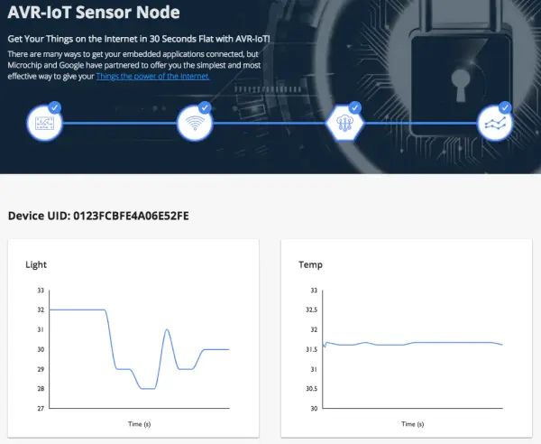
You should see a drive named “CURIOSITY” appear on your PC. Open this drive and double-click the file labeled “CLICK-ME.HTM”. This will direct you to Microchip’s Google Cloud demonstration page. Here, you can generate a Wi-Fi credentials file for the board.
Scroll down to the “Wireless Network Connection” section. Enter your Wi-Fi SSID, security type, and password. Click “Download Configuration” to save the “WIFI.CFG” file. Drag and drop this file onto the CURIOSITY drive to configure the board’s Wi-Fi settings.
Monitor the board’s LEDs for status cues: blue for Wi-Fi connection, green for successful sandbox connection, yellow for data transmission. A red LED indicates an error. The demo page should display live sensor readings from the board once connected.
Later, we will reconfigure the board to connect to our own Google Cloud project instead of the pre-authenticated Microchip sandbox shown here. For now, this demonstrates basic Wi-Fi and cloud functionality out of the box.
The Setup (Software)
Atmel Studio 7
In this step, we will download and install Atmel Studio 7 on a Windows PC. First, go to the Atmel Studio website and locate the “Downloads” section. Here, you can choose between the smaller “web installer” which requires an active Internet connection during installation, or the larger complete “offline installer” package.
Download whichever installer you prefer, then run it and follow the prompts in the installation wizard. Be sure to check the box for “AVR 8-bit MCU” in the architecture selection step. Optionally, you may also enable AVR 32-bit MCU, SMART ARM MCU, and related frameworks if desired, but they are not required here.
Once installation is complete, launch Atmel Studio 7. You should see the start page open. Your menu items may vary slightly depending on any additional optional components selected during setup.
For our purposes, only the 8-bit AVR support is needed to develop for this board using the free IDE. We are now ready to begin creating projects within Atmel Studio 7.
With Atmel Studio now running and the start page displayed, disconnect the USB cable from the AVR-IoT WG board. Wait several seconds, then reconnect the USB cable.
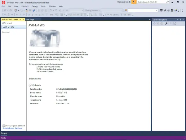
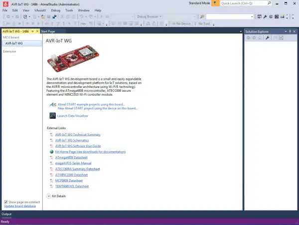
A new window should appear within Atmel Studio providing information about the connected board. As shown in Figure 4, board details are presented that can be expanded further by clicking the “Kit Details” option. This verification ensures our development environment properly detects the microcontroller board plugged into the computer.
Locate the “Update board database” link in the bottom-left section. Clicking this requires an active Internet connection to retrieve supplemental board details from Microchip’s servers.
Once clicked, disconnect then reconnect the USB cable after a short wait, as before. You should now see an expanded view with additional technical information and documentation about the board (Figure 5).
This “board database” update ensures Atmel Studio has the most complete information available to support development activities on this specific microcontroller kit.
Update Device Pack for ATmega4808
From the Tools menu, select Device Pack Manager. Click the “Check for Updates” button to search Microchip’s servers.
Enter “4808” into the search box and press enter. Scan the results list carefully for any updates that may relate to the ATmega4808 microcontroller, even if the description does not explicitly state the part number.
If an applicable update is shown, click the “Install” button to commence the download and installation process. Atmel Studio may then ask you to restart the application in order to finalize the update.
Checking for and applying any relevant device pack updates will help ensure the development tools have the latest definitions and support for our target ATmega4808 chip.
Atmel START
Now we will initialize a project using Atmel START, a tool within Atmel Studio for streamlining embedded application development.
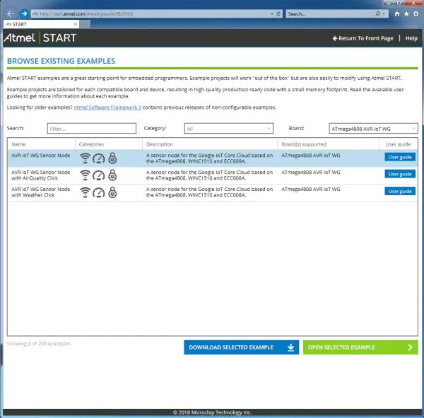
On the information page displayed for the AVR-IoT WG board, click the link labeled “Atmel START example projects using this board…”. This will direct your web browser to the dedicated Atmel START portal page for this kit (Figure 6).
Selecting this option launches us directly into the online Atmel START guide, allowing easy access to preconfigured example programs we can import straight into our workspace to begin experimenting with the hardware.
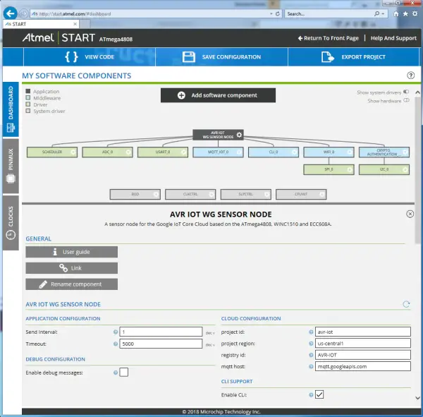
On the Atmel START page for the AVR-IoT WG board, select the “AVR IoT WG Sensor Node” example project. Then click the “Open Selected Example” button.
Atmel START will compile the necessary code components and present a project configuration screen where default parameters can be customized if needed (Figure 7). However, we will keep the default settings for now.
Click the browser’s “Back” button to return to the main Atmel START page for this board (Figure 6). Confirm if asked to return without saving changes. If you have trouble navigating back, simply close and reopen the browser then navigate from the Atmel Studio information page we started from.
By walking through this example without modification, we familiarize ourselves with Atmel START’s workflow before importing a project into our workspace.
Download the Project
On the Atmel START page for the AVR-IoT WG board (Figure 6), select the “AVR IoT WG Sensor Node” example again. Now click the “Download Selected Example” button.
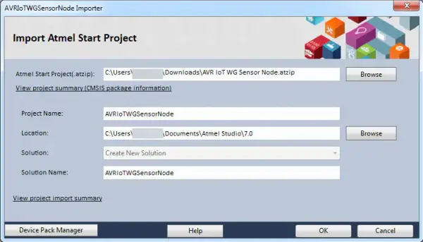
This will prompt you to save a file called “AVR IoT WG Sensor Node.atzip”, which signifies an Atmel Studio project archive. The .atzip extension means it contains all the necessary components to open as a project within our IDE.
Double-click this downloaded file to initiate the project import process into Atmel Studio. You’ll see a window with default import settings prepopulated (Figure 8). Click “OK” to complete bringing the example into our development environment.
We have now seamlessly transitioned the online example into a project we can build and customize directly within Atmel Studio on our local machine.
If you get a warning messages about necessary device updates, it may be because there are Device Pack updates you haven’t installed yet.
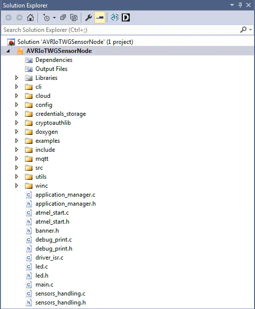
After the project is imported, it will appear in the Solution Explorer pane (Figure 9).
Verify Building the Project Code
Let’s do a test build of the project in its current state to confirm everything imported correctly.
Select “Build > Build Solution” from the top menu. This will initiate a compilation of all the project code and files. The build should complete successfully, although you may see some warning messages displayed – these can be addressed later.
For now, it’s reassuring to know the example application built cleanly without errors on our local system. We’ll leave further exploration of the source code until after setting up our Google Cloud environment, which is the next step.
Doing this initial test build verifies our development tools and example project are ready to be customized and expanded upon going forward.
Google Cloud Platform
Here is one way to rephrase the passage in terms of queries and responses related to setting up the Google Cloud IoT environment:
Query: What is the first step to make the board known to Google Cloud IoT and add its digital key?
Response: The first step is to use a web browser to navigate to the Google Cloud console at https://console.cloud.google.com.
Query: What do you need to do once at the Google Cloud console?
Response: Once at the Google Cloud console, you need to establish a Google Cloud login account if you do not already have one. You also need to create a new cloud project with billing support enabled at the project level.
Query: Where are the remaining steps performed?
Response: The rest of the steps to make the board known to Google Cloud IoT and add its digital key are performed within the newly created cloud project.
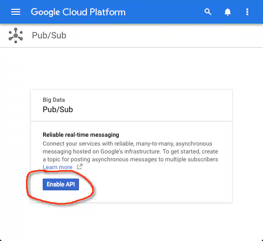
Enable Pub/Sub API
Navigate to the Pub/Sub service and enable the Pub/Sub API (Figure 10).
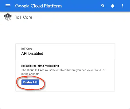
Enable IoT Core API
Navigate to the IoT Core page and enable the IoT Core API (Figure 11).
Create Device Registry
While still in the IoT Core service, click “Create a device registry” (Figure 12).
