Summary of Build Your Own Microcontroller Based PID Control Line Follower Robot (LFR) – Second Part
The article details building a microcontroller-based Line Follower Robot (LFR) using the Atmel AVR ATMega168, implementing industrial-standard PID control. It highlights features like EEPROM storage for PID tuning, infrared sensors with MCP23008 I2C I/O expander, MAX756 DC-DC step-up for stable power, ADC for speed control, and PWM to drive L293D motor driver ICs. The BRAM II chassis uses an acrylic base, dual decks for components, and geared DC motors powered by 3xAA batteries with a boost converter. This design improves robustness, flexibility, and precise motor control over simpler transistor-based versions.
Parts used in the Line Follower Robot (BRAM II):
- Atmel AVR ATMega168 microcontroller
- Infrared reflective sensors (five)
- Microchip MCP23008 8-bit I2C I/O expander chip
- Maxim MAX756 DC-DC step-up converter
- SGS-Thomson L293D motor driver IC
- Two geared DC motors with wheels (4.5 to 5 V, 25-30mA)
- Acrylic sheet for chassis
- 3 x 1.5V AA battery holder with on-off switch
- Plastic bead (for caster)
- Paper clip (for caster)
- Nuts, bolts, and PCB standoffs
- AVRJazz Mega168 development board
One of the interesting parts in building the Line Follower Robot is; you could start it with a very simple version by using just two transistors with the LED and LDR for sensor (Build Your Own Transistor Based Mobile Line Follower Robot – First Part) and enhance it to the programmable version that use microcontroller as the brain for controlling the robot. The reason of using the microcontroller for the Line Follower Robot is we need to make more robust, reliable and flexible robot which you could not have it from the discrete electronics component robot without changing most of the electronic circuit design.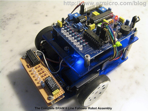
The advantages in building the microcontroller based Line Follower Robot (LFR) is we could take the advantage of microcontroller’s ALU (Arithmetic Logic Unit) to compute mathematics equation to perform the industrial standard Proportional, Integral and Derivative control or known as PID control. On this tutorial we will learn to build the LFR using the powerful Atmel AVR ATMega168 microcontroller and at the same time we will learn to utilize many of the AVR ATMega168 microcontroller sophisticated features to support our Line Follower Robot.
Now let’s check out all the exciting features of this Line Follower Robot that we are going to build:
- Fully implement the industrial standard Proportional, Integral and Derivative (PID) control with flexible PID tuning parameter using the AVR ATMega168 UART peripheral and store the parameter to the AVR ATMega168 microcontroller build-in 512 Bytes EEPROM
- Use five infra red reflective object sensor for the black line sensor with Microchip MCP23008 8-bit I2C (read as I square C) I/O expander chip to talk to the AVR ATMega168 Microcontroller I2C peripheral
- 4.5 Volt to 5 Volt DC to DC Step-Up using Maxim MAX756 for powering both the electronics circuits and the DC motors. This will ensure the electronics circuits and the DC motors keep working properly even though the battery voltage level drops below 4.5 Volt.
- Use the AVR ATMega168 ADC (Analog to Digital Converter) peripheral to control the maximum speed of the robot.
- Use the AVR ATMega168 PWM (Pulse Width Modulation) peripheral to drive the SGS-Thomson L293D chip to control the DC motors speed
BRAM II Chassis Construction
The first version of BRAM (Beginner’s Robot Autonomous Mobile), used CD/DVD for the chassis; in this version of BRAM, I use the acrylic as the base for the chassis; which is easy to shape, drill and it came with transparent look and many color to choose too. You could read more information about the first BRAM version on my previous posted blog Building BRAM your first Autonomous Mobile Robot Using Microchip PIC Microcontroller.
BRAM II construction material parts:
- Acrylic for the BRAM chassis
- Two geared DC motors with wheels rated 4.5 to 5 volt (25-30mA) with the wheel or you could use the modified servo motor (it’s a servo motor without the electronics’s control board)
- One 3 x 1.5 volt AA battery holder with on-off switch
- One plastic bead (usually it use for the neck less) and one paper clip for the caster
- Enough nuts, bolts and PCB (printed circuit board) standoff.
BRAM construction consists of two decks, where the lower deck is used to hold the battery, DC motors and the sensor circuit while the upper deck is used to hold the motor controller circuit and the AVRJazz Mega168 board.
Finally put the AVRJazz Mega168 board on top of the upper deck and connect all the connectors from the Motor Control Circuit and Sensor Circuit to the AVRJazz Mega168 board, now you are ready to program the robot.
BRAM II Electronic Circuit and Program
BRAM II use quite sophisticated power mechanism circuit as well as the line sensor circuit design to make it more robust line follower robot.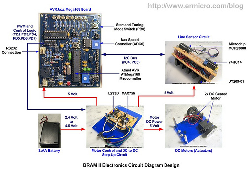
The 3xAA battery is the main power source for both the electronics circuits and the DC motors, because the Line Follower Robot need to accurately control the motor speed and tracking the line; therefore BRAM II design use DC to DC step-up circuit to boost 4.5 volt level up to the 5 volt level using the Maxim MAX756, you could read more about MAX756 in my previous posted blog Powering your Microcontroller’s Based Project. The advantages of using the power boost is all the electronics circuits and DC motors will guarantee to get proper voltage level even though the main power source theoretically drops down to 2 volt level; although I’ve never try this.
For more detail: Build Your Own Microcontroller Based PID Control Line Follower Robot (LFR) – Second Part