Summary of Build a Motion Control Rig for Time-Lapse Photography
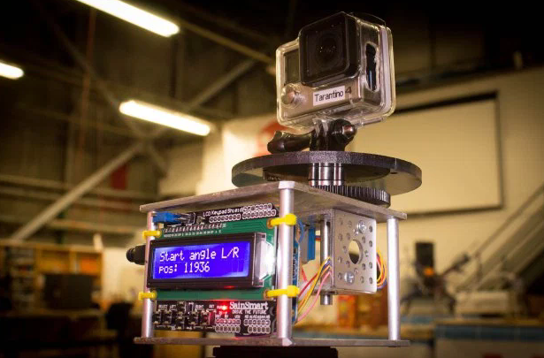
This article describes a DIY motion control rig for time-lapse photography using an Arduino microcontroller and stepper motor. The device enables precise camera panning with adjustable start/stop positions and durations from five minutes to 12 hours, powered by any USB source like a portable battery brick. The chassis is constructed from aluminum bar stock cut into 4x4 inch squares, requiring precision drilling and threading.
Parts used in the Motion Control Rig:
- Arduino microcontroller
- Stepper motor
- LCD keypad shield
- Aluminum bar stock
- Drilling template
- Contact adhesive
- Drill press
- Portable USB power source
If you dig around in your camera’s settings long enough, you’re almost assured to find that it has a mode to create time-lapse videos — those magical, time compressing movies that can turn any hillside or street corner into a lightning-paced dreamscape.
Time-lapse videos by themselves are easy enough to make, but if you do enough of them, you’re likely to get bored with the motionless camera framing. But what can you do here? Having a moving time lapse means moving a camera very predictably, and very, very slowly. You can build a simple panning rig out of a mechanical kitchen timer, but that’s only good if your time lapse is an hour or less, plus, the camera will rotate the full 360 degrees in that hour, further limiting your control.
In this project, we’ll be using an Arduino microcontroller and a stepper motor to precisely control the panning of a camera during a time lapse. Using this LCD keypad shield as an interface, we can precisely set our starting and stopping positions, as well as setting the duration of our time lapse — anywhere between five minutes and 12 hours. The device can be powered via any USB power source, and those portable USB bricks used to keep your smartphone alive during long days will work perfectly, and can power the device for up to 12 hours.
- We’ll begin by drilling holes into the top and bottom plates that make up the chassis. Start by cutting your aluminum bar stock into two 4”×4” squares and sand down any burrs or rough edges.
- Precision drilling matters here, so print out the provided drilling template and apply it to the two squares using contact adhesive, and if you have access to a drill press, use that to drill the holes.
- Countersink all of the ⅛” holes drilled, and tap the hole in the center of the bottom plate with ¼ – 20 threads. Remove the templates and any remaining glue residue.
For more detail: Build a Motion Control Rig for Time-Lapse Photography
- How does this project improve standard time-lapse videos?
It allows for predictable, slow camera movement to avoid boring motionless frames. - What range of durations can the device support?
The duration can be set anywhere between five minutes and 12 hours. - Can I use a smartphone battery to power the device?
Yes, portable USB bricks used for smartphones will work perfectly. - What material is used for the chassis plates?
The top and bottom plates are made from aluminum bar stock cut into 4x4 inch squares. - How do you ensure hole alignment during construction?
A provided drilling template is applied using contact adhesive before drilling. - What specific thread size is tapped in the center of the bottom plate?
The center hole is tapped with ¼ - 20 threads. - Does the mechanical kitchen timer method offer better control than this project?
No, the timer only works for an hour or less and forces a full 360-degree rotation.