Summary of Build your own stopwatch using Maxim MAX7219 Serially Interfaced, 8-Digit LED Display Drivers
This article details building a stopwatch using an Atmel AVR ATmega328P microcontroller and a Maxim MAX7219 chip to drive an 8-digit seven-segment display via SPI. The project utilizes TIMER2 for timing, pin change interrupts for button detection, and ADC for brightness control. It features start/stop functionality, background counting, intensity adjustment, and a reset option.
Parts used in the Stopwatch Project:
- One Maxim MAX7219 Serially Interfaced, 8-Digit LED Display Drivers
- Two common cathode 4-Digits seven segment LED displays
- One 10K Ohm Resistor
- One 0.1uF Capacitor
- AVRJazz 28PIN development board based on AVR ATmega328P
- Atmel AVR Studio 6.0 coding environment
- STK500 programmer with AVRJazz 28PIN board STK500 v2.0 bootloader
- Atmel AVR ATmega328 Datasheet
- Maxim MAX7219 Datasheet
One of the basic usage of the TIMER peripheral on every microcontroller is to provide the accurate timing mechanism. Using the TIMER peripheral as the basic timing, we could easily develop a stopwatch and display it to the 8-Digit seven segment numeric LED display. Thanks to the Maxim MAX7219 chip which enable us to interface this 8-Digit seven segment LED display much easier using just three wires of the SPI (serial peripheral interface) to display the hour, minute, second, and hundredth of seconds to the 8-Digit seven segments LED display.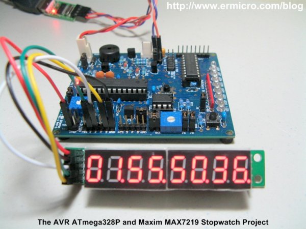
On this tutorial we will learn to utilize the Atmel AVR ATMega328P microcontroller SPI peripheral to communicate with the Maxim MAX7219 chip. The AVR ATmega328P SPI peripheral will be configured as a master and Maxim MAX7219 as the SPI device slave; you could read more about the SPI in Using Serial Peripheral Interface (SPI) Master and Slave with Atmel AVR Microcontroller project on this blog. A simplified electronic schematic of this project is shown in this following picture.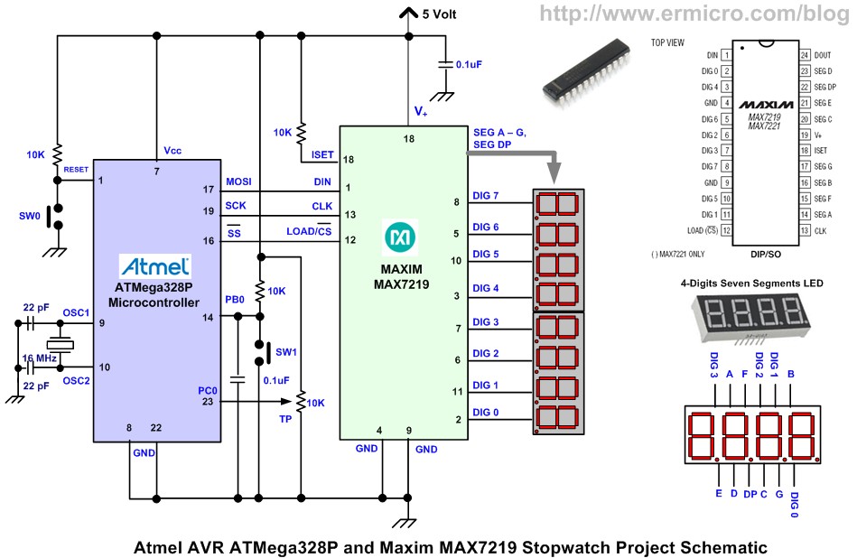
The following is the list of hardware, software, and references used to build this project:
1. One Maxim MAX7219: Serially Interfaced, 8-Digit LED Display Drivers
2. Two common cathode 4-Digits seven segment LED display
3. One Resistor: 10K Ohm
4. One Capacitors 0.1uF
5. AVRJazz 28PIN development board from ermicro which is based on the AVR ATmega328P microcontroller.
6. Atmel AVR Studio 6.0 for coding and debugging environment
7. STK500 programmer from AVR Studio 6.0, using the AVRJazz 28PIN board STK500 v2.0 bootloader
8. Atmel AVR ATmega328 and Maxim MAX7219 Datasheet
The stopwatch project that we are going to build has these following features:
- Stopwatch counting up to hundredth of second when the SW1 is pressed
- Pressing the SW1 once will freeze the counting display while continuing counting in the background, pressing the SW1 again will continue to display the stopwatch counting
- Adjust the intensity of the 8-Digits seven segment LED display using the trimmer potentiometer (TP).
- Reset the stopwatch counting by pressing the SW0.
In order to accomplish this project, we will use the AVR ATmega328P 16-bit TIMER2 peripheral in compare match mode as the heart beat of the counting mechanism, the pin change interrupt is used to detect the SW1 switch, and the ADC peripheral is used to adjust the 8-Digit seven segment LED display brightness. This project also serves as a good example of how we use many of the powerful AVR ATmega328P microcontroller features at the same time. The following is the complete C code for this project:
For more detail: Build your own stopwatch using Maxim MAX7219 Serially Interfaced, 8-Digit LED Display Drivers
- How is the 8-digit display driven?
The Maxim MAX7219 chip interfaces with the microcontroller via three SPI wires. - What timer peripheral controls the counting mechanism?
The AVR ATmega328P 16-bit TIMER2 peripheral operates in compare match mode. - How does the system detect the SW1 switch press?
A pin change interrupt is used to detect the SW1 switch. - Can the display brightness be adjusted?
Yes, the ADC peripheral adjusts the intensity using a trimmer potentiometer. - What happens when SW1 is pressed once?
Pressing SW1 freezes the display while counting continues in the background. - How do you reset the stopwatch?
The stopwatch counting resets by pressing the SW0 button. - What is the role of the SPI master configuration?
The AVR ATmega328P SPI peripheral is configured as a master to communicate with the MAX7219 slave. - Which software is used for coding this project?
Atmel AVR Studio 6.0 is used for the coding and debugging environment.