Summary of Building a Basic Calculator using ATmega32 Microcontroller
This article guides building a basic calculator using an ATmega32 microcontroller, a 4x4 keypad for input, and a 16x2 LCD for output. It covers hardware connections (keypad to PORTC, LCD to PORTA), required components, and full C source files for main, keypad, LCD, sbit, and calculation modules. The tutorial explains compiling and uploading code with an AVR programmer and testing basic arithmetic operations, plus error handling and display routines.
Parts used in the ATmega32 Calculator:
- ATmega32 microcontroller
- 16x2 LCD display
- 4x4 keypad
- Resistors
- Capacitors
- Power supply (reliable)
- AVR ISP programmer (e.g., AVR MKII)
- Wiring/PCB or breadboard
A calculator stands as a fundamental tool in daily life, and building one from scratch can serve as both an engaging and educational project. Utilizing the ATmega32 microcontroller presents a potent avenue, offering programmability for a diverse array of functionalities. This blog post aims to guide you through constructing a straightforward calculator using the ATmega32 microcontroller.
Within this tutorial, we demonstrate the creation of a basic calculator employing the ATmega32 microcontroller. This setup integrates the Atmega32 as the calculator’s core processor and controller. Input is received from a 4×4 keypad, and the output is showcased on a 16×2 LCD (Liquid Crystal Display). This project serves as an instructive tool, illustrating the process of interfacing input and output devices with a microcontroller. It delves into writing C program code for keypad input, executing mathematical computations, and displaying the results on an LCD output device.
To embark on this calculator-building journey, the initial step involves procuring the essential components. The primary component, the ATmega32 microcontroller, is readily available from various electronics suppliers. Additionally, you’ll require a 16×2 LCD display, a keypad, and a selection of supplementary components such as resistors, capacitors, and a reliable power supply.
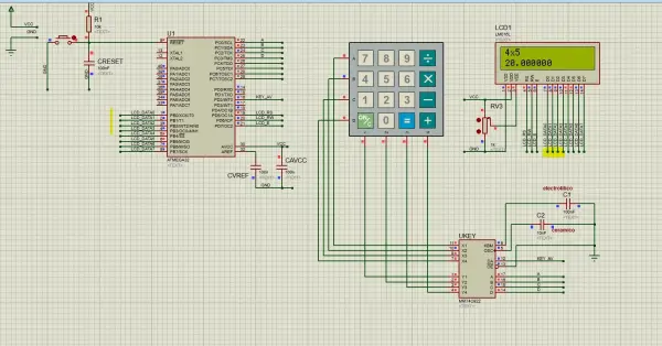
Below, you’ll find the circuit schematic depicting the configuration for the ATmega32 calculator.
In the depicted circuit diagram, the 4×4 keypad interfaces with port C of the microcontroller, while the 16×2 LCD connects to port A.
Once you’ve gathered all the necessary components, the assembly process for the calculator can commence. The ATmega32 microcontroller serves as the central processing unit, responsible for executing calculations and displaying results on the LCD screen. Utilizing the keypad, users input numbers and operations, and its connection to the ATmega32 microcontroller is illustrated in the aforementioned circuit diagram.
Upon completing the hardware assembly, programming the ATmega32 microcontroller becomes the next step. This programming task involves using languages such as C, requiring a programmer like AVR MKII to upload the code to the microcontroller. For detailed guidance on code uploading, refer to the tutorial “How to Program ATmega328p using ATMEL Studio & AVR ISP MKII.”
The program code for this calculator encompasses several C program files, including those for actual calculations, keypad input reading, LCD output writing, the primary C program, and an sbit C file. The files include:
1. Primary C program
2. Keypad header and C program
3. LCD header and C program
4. Sbit header program
5. Calculation header and C program
These specific calculator programming files are provided below for reference.
1. main C program
The main C program code is below.
#include <avr/io.h>
#include
#include <util/delay.h>
#include “lcd.h”
#include “sbit.h”
#include “keypad.h”
#include “calc.h”
int main(void){
lcdinit();
unsigned char key; // Key char for keeping record of pressed key
int num1, num2; // First number, second number
char func; // Function to be performed among two numbers
lcdgoto(5,1);
lcdstr(“ATmega32 “);
lcdgoto(4,2);
lcdstr(“Calculator”);
_delay_ms(2000);
lcdclear();
while(1)
{
key = keypress(); //get numb1
lcdcmd(0x01); // Clear LCD screen
lcdchar(key); // Echo the key pressed to LCD
num1 = get_num(key); // Get int number from char value, it checks for wrong input as well
if(num1 != Error) // If correct input then proceed, num1==Error means wrong input
{
key = keypress(); //get function
lcdchar(key); //Echo the key pressed to LCD
func = get_func(key); //it checks for wrong func
if(func!=’e’) //if correct input then proceed, func==’e’ means wrong input
{
key = keypress(); //get numb2
lcdchar(key); //Echo the key pressed to LCD
num2 = get_num(key); //Get int number from char value, it checks for wrong input as well
if(num2!=Error) //if correct input then proceed, num2==Error means wrong input
{
key = keypress(); //get equal sign
lcdchar(key); //Echo the key pressed to LCD
if(key == ‘=’) //if = is pressed then proceed
{
switch(func) //switch on function
{
case ‘+’:
disp_num(num1+num2);
break;
case ‘-‘:
disp_num(num1-num2);
break;
case ‘x’:
disp_num(num1*num2);
break;
case ‘/’:
disp_num(num1/num2);
break;
}
}
else //key other then = here means error wrong input
{
if(key == ‘C’) //if clear screen is pressed then clear screen and reset
lcdcmd(0x01); // Clear LCD screen
else
DispError(0); //Display wrong input error
}
}
}
}
}
return 0;
}
This main program code uses keypad, lcd ,sbit and calculator program code as follows.
2. keypad header and C program
The keypad program codes comprise a header file named keypad.h and a corresponding c program file named keypad.c. These files manage the functionality of the keypad within the main.c program mentioned earlier. They contain various functions that are invoked within the main program code. These specific program codes are outlined below.
a. keypad .h
#include <avr/io.h>
#include <util/delay.h>
unsigned char keypress();
b. keypad.c
#include <avr/io.h>
#include “util/delay.h”
#include “sbit.h”
#define R1 SBIT(PORTC, 0)
#define R2 SBIT(PORTC, 1)
#define R3 SBIT(PORTC, 2)
#define R4 SBIT(PORTC, 3)
#define c1 SBIT(PINC, 4)
#define c2 SBIT(PINC, 5)
#define c3 SBIT(PINC, 6)
#define c4 SBIT(PINC, 7)
unsigned char keypress(void)
{
DDRC=0b00001111;
PORTC=0b11110000;
while (1)
{
R1=0; R2=1; R3=1; R4=1;
_delay_us(50);
if (c1==0){while (c1==0);return (‘7’);}
if(c2==0){while (c2==0); return (‘8’);}
if (c3==0){while (c3==0); return (‘9’);}
if(c4==0){while (c4==0);return (‘/’);}
R1=1; R2=0; R3=1; R4=1;
_delay_us(50);
if (c1==0){while (c1==0); return (‘4’);}
if(c2==0){while (c2==0); return (‘5’);}
if(c3==0){while (c3==0); return (‘6’);}
if(c4==0){while (c4==0); return (‘x’);}
R1=1; R2=1; R3=0; R4=1;
_delay_us(50);
if (c1==0){while (c1==0); return (‘1’);}
if (c2==0){while (c2==0); return (‘2’);}
if (c3==0){while (c3==0); return (‘3’);}
if (c4==0){while (c4==0); return (‘-‘);}
R1=1; R2=1; R3=1; R4=0;
_delay_us(50);
if (c1==0){while (c1==0); return (‘C’);}
if (c2==0){while (c2==0); return (‘0’);}
if (c3==0){while (c3==0); return (‘=’);}
if (c4==0){while (c4==0); return (‘+’);}
}
}
3. LCD header and C program
The programming code for the LCD component includes both a header file, lcd.h, and a C program file, lcd.c. These files govern the functionality of the LCD within the main.c program mentioned earlier. They contain functions that are invoked within the primary C program. The coding details for these specific files are furnished below.
a. lcd.h
#include <avr/io.h>
void lcdinit();
void lcdcmd(unsigned char);
void lcdchar(unsigned char);
void lcdstr(char *);
void latch(void);
void lcdgoto(uint8_t , uint8_t );
void lcdclear();
b.lcd.c
#include <avr/io.h>
#include <util/delay.h>
#include “lcd.h”
#define E (1<<PA3)
#define RW (1<<PA2)
#define RS (1<<PA1)
void lcdinit(){
//initialize PORTs for LCD
DDRA |= (1<<PA1) | (1<<PA2) | (1<<PA3) | (1<<PA4) | (1<<PA5) | (1<<PA6) | (1<<PA7); //make output for E,RW,RS and 4 bit Data
//Send Pulse to Latch the data
latch();
_delay_ms(2); //delay for stable power
// Command to set up the LCD
lcdcmd(0x33);
_delay_us(100);
lcdcmd(0x32);
_delay_us(100);
lcdcmd(0x28); // 2 lines 5×7 matrix dot
_delay_us(100);
//lcdcmd(0x0E); // display ON, Cursor ON
lcdcmd(0x0C); // display ON, Cursor ON
_delay_us(100);
lcdcmd(0x01); //clear LCD
_delay_ms(20); //wait
lcdcmd(0x06); //shift cursor to right
_delay_ms(100);
}
void latch(void){
PORTA |= E; //send high
_delay_us(500); //wait
PORTA &= ~E; //send low
_delay_us(500); //wait
}
void lcdcmd(unsigned char cmd){
PORTA = (PORTA & 0x0F) | (cmd & 0xF0); // send high nibble
PORTA &= ~RW; //send 0 for write operation
PORTA &= ~RS; //send 0 to select command register
latch(); //latch the data
PORTA = (PORTA & 0x0F) | (cmd<<4); //send low nibble
latch(); //latch the data
}
void lcdchar(unsigned char data){
PORTA = (PORTA & 0x0F) | (data & 0xF0); // send high nibble
PORTA &= ~RW; //send 0 for write operation
PORTA |= RS; //send 1 to select data register
latch();
PORTA = (PORTA & 0x0F) | (data<<4); // send high nibble
latch();
}
void lcdstr(char *str){
unsigned char k=0;
while(str[k] != 0){
lcdchar(str[k]);
k++;
}
}
void lcdgoto(unsigned char x, unsigned char y){
unsigned char firstcharadr[] = {0x80, 0xC0, 0x94, 0xD4};
lcdcmd(firstcharadr[y-1] + x-1);
_delay_us(1000);
}
void lcdclear(){
lcdcmd(0x01);
_delay_ms(10);
}
4. sbit header program
Another integral component utilized in this calculator program is the sbit.h program file. This particular file functions by generating a macro, enabling the referencing of a singular bit within a chosen port.
#ifndef _sbit_h_
#define _sbit_h_
struct bits {
uint8_t b0:1;
uint8_t b1:1;
uint8_t b2:1;
uint8_t b3:1;
uint8_t b4:1;
uint8_t b5:1;
uint8_t b6:1;
uint8_t b7:1;
} __attribute__((__packed__));
#define SBIT(port,pin) ((*(volatile struct bits*)&port).b##pin)
#endif
5. calculation header and C program
Finally, an additional set of programming code files is dedicated to the calculator—namely, the calc.h and calc.c files. These specific program codes manage the computational functionalities within the calculator. The functions embedded in these files are subsequently utilized within the main C program.
a.calch
#include <avr/io.h>
#include <util/delay.h>
#define Error 13
int get_num(unsigned char);
unsigned char get_func(unsigned char);
void DispError(int);
void disp_num(int);
b.calc.c
#include <avr/io.h>
#include <util/delay.h>
#include “calc.h”
#include “lcd.h”
int get_num(unsigned char ch) //convert unsigned char into int
{
int num = 0;
switch(ch)
{
case ‘0’:
num = 0;
break;
case ‘1’:
num = 1;
break;
case ‘2’:
num = 2;
break;
case ‘3’:
num = 3;
break;
case ‘4’:
num = 4;
break;
case ‘5’:
num = 5;
break;
case ‘6’:
num = 6;
break;
case ‘7’:
num = 7;
break;
case ‘8’:
num = 8;
break;
case ‘9’:
num = 9;
break;
case ‘C’:
lcdcmd(0x01);
num = Error;
break; //this is used as a clear screen and then reset by setting error
default:
DispError(0);
num = Error;
break; //it means wrong input
}
return num;
}
unsigned char get_func(unsigned char chf) //detects the errors in inputted function
{
if(chf==’C’) //if clear screen then clear the LCD and reset
{
lcdcmd(0x01); //clear display
return ‘e’;
}
if( chf != ‘+’ && chf != ‘-‘ && chf != ‘x’ && chf != ‘/’ ) //if input is not from allowed funtions then show error
{
DispError(1);
return ‘e’;
}
return chf; //function is correct so return the correct function
}
void DispError(int numb) //displays differet error messages
{
unsigned char msg1[] = {“Wrong Input”};
unsigned char msg2[] = {“Wrong Function”};
lcdcmd(0x01); //clear display
switch(numb)
{
case 0:
lcdstr(msg1);
break;
case 1:
lcdstr(msg2);
break;
default:
lcdstr(msg1);
break;
}
}
void disp_num(int numb) //displays number on LCD
{
unsigned char UnitDigit = 0; //It will contain unit digit of numb
unsigned char TenthDigit = 0; //It will contain 10th position digit of numb
if(numb<0) {
numb = -1*numb; // Make number positive
lcdchar(‘-‘); // Display a negative sign on LCD
}
TenthDigit = (numb/10); // Find out Tenth Digit
if( TenthDigit != 0) // If it is zero, then don’t display
lcdchar(TenthDigit+0x30); // Make Char of TenthDigit and then display it on LCD
UnitDigit = numb – TenthDigit*10;
lcdchar(UnitDigit+0x30); // Make Char of UnitDigit and then display it on LCD
}
Upon successful code upload, the calculator can undergo testing by executing basic arithmetic operations like addition, subtraction, multiplication, and division. If all functions properly, the LCD display will exhibit the calculated results.
View the video demonstration below to observe the operational functionality of this calculator built around the ATmega32 microcontroller.
In summary, crafting a calculator using an ATmega32 microcontroller proves to be an engaging and enlightening endeavor, offering insights into both microcontroller programming and electronic circuitry design. The ATmega32 microcontroller’s adaptability and robust capabilities allow programming for diverse functionalities, rendering it an excellent option for constructing a calculator. With dedicated time and effort, you can create a functional calculator capable of handling basic arithmetic operations, providing a hands-on learning experience in microcontroller-based calculation.
- What microcontroller is used in this calculator project?
The ATmega32 microcontroller is used as the core processor and controller. - How is the keypad connected to the microcontroller?
The 4x4 keypad interfaces with PORTC of the ATmega32 as shown in the circuit diagram and managed by keypad.c and keypad.h. - How is the LCD connected to the microcontroller?
The 16x2 LCD is connected to PORTA of the ATmega32 and controlled via lcd.c and lcd.h functions. - What programming language and tools are used to program the ATmega32?
The code is written in C and uploaded using an AVR programmer such as AVR MKII, following instructions like How to Program ATmega328p using ATMEL Studio & AVR ISP MKII. - Which source files make up the calculator program?
The project includes main C program, keypad.h/keypad.c, lcd.h/lcd.c, sbit.h, and calc.h/calc.c. - Can this calculator perform basic arithmetic operations?
Yes, it supports addition, subtraction, multiplication, and division as implemented in the main program switch statement and calc modules. - How does the project handle wrong input or functions?
Error handling is implemented: get_num returns Error for invalid numbers, get_func returns e for invalid functions, and DispError displays Wrong Input or Wrong Function on the LCD. - What does the sbit.h file provide?
sbit.h defines a macro SBIT to reference individual bits of a port, enabling single-bit access used in keypad scanning. - How are results displayed on the LCD?
Results are shown using disp_num from calc.c, which converts integers into characters and sends them to the LCD via lcdchar and related lcd functions. - Is there a demonstration of the working calculator?
The article includes a video demonstration link to observe the operational functionality of the ATmega32 calculator.