Summary of Building a Calculator Using Keypad-Based Peripherals
This laboratory session guides the construction of an 8051-based integer calculator using a numeric keypad for input and an LCD for output. The system scans a 4x4 matrix keypad to capture two operands and an operator, then computes and displays the result. The project involves programming the microcontroller via a development board and utilizing specific hardware components like resistors, oscillators, and programmers to create a standalone embedded solution.
Parts used in the Integer Calculator Project:
- One-thousand-ohm resistor
- Numeric keypad
- Liquid Crystal Display (LCD)
- Crystal oscillator running at 12 megahertz
- Power supply operating at 5 volts
- Philips PDS51 development board
- LCPX5X40 programmer
Introduction
In this laboratory session, your task involves constructing a basic calculator utilizing the keypad as an input mechanism and the LCD as an output display unit. Following the debugging and testing phase of your program, the final step will be to program a standalone 8051 chip with the compiled code.
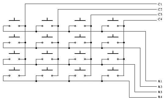
Keypads commonly serve as the primary input interface for embedded microcontrollers. They are composed of multiple switches organized in a row/column configuration, as depicted in Figure 1.
To scan the keypad, the microcontroller outputs a nibble to set one specific column low and then checks the rows to detect any pressed buttons within that column. The rows are maintained at a logic high level by the internal weak pull-ups in the 8051 ports. Thus, when no buttons are pressed, the microcontroller registers a logic high on each pin linked to the keypad rows. The nibble directed to the columns consistently contains only a single 0. The microcontroller can identify a 0 on any row pin only when a keypad button is pressed, connecting the column set to 0 to a particular row. By discerning the column at a 0-level and the row reading 0, the controller can ascertain the specific key pressed. The pin order for the keypad is: R1, R2, R3, R4, C1, C2, C3, C4 from left to right.
Assignment
In this laboratory task:
Your objective is to create an integer calculator utilizing a keypad for input. Your design must have the capability to interpret both the operands (whole numbers from 0 to 9) and the operator entered through the keypad. You have the freedom to devise any sequence of input. For instance, you might choose to follow this input sequence:
Select the initial operand
Choose the operator
Select the second operand
Apparatus Required:
1. One-thousand-ohm resistor (1)
2. Numeric keypad
3. Liquid Crystal Display (LCD)
4. Crystal oscillator running at 12 megahertz
5. Power supply operating at 5 volts
6. Philips PDS51 development board
7. LCPX5X40 programmer
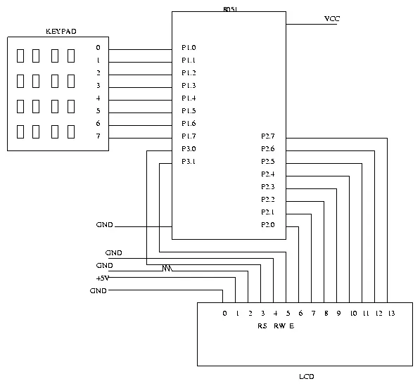
Schematic:
Program:
/* To implement a integer calculator using a keypad and LCD */

#pragma SMALL DB OE
#include <reg51.h>
#include "io.h"

/* The functions to initialize and control the LCD are assumed to be in the file io.c */

/* Function to output the decimal value of the result on the LCD */
void PrintInt(int i) {
     .
     .
     .
}

/* Routine to scan the key pressed */
unsigned char key_scan()
{
       unsigned char i, j, temp1, temp2;

        while( 1 ) /* keep waiting for a key to be pressed */

                for(i=0; i<4; i++) {

                        /* Set each row to 0 */
                        P1 = 0xff & ~(1<<i);

                        /* Scan each column to see which key was pressed */
                        for (j=4; j<8; j++) {

                              /* Code to determine the position of the
                                 key which was pressed */
                              /* return(position) */
                        }
                }
}

void main() {

        /* You can have a conversion table to convert the key position into a
           valid number which indicates the operator or operand value. For eg:
           the numbers 0 to 9 are valid operands and 100 to 103 denote
           addition, subtraction, multiplication and division respectively */

        char conv_table[] = {

                 1, 2,  3, 100 /* add */,
                 4, 5,  6, 101 /* sub */,
                 7, 8,  9, 102 /* mul */,
                -1, 0, -1, 103 /* div */
        };
        char num1, num2, op;
        int result;

        InitIO();

        while(1) {

                ClearScreen();

                /* read num1 */
                GotoXY(0, 0);
                PrintString("num1 : ");
                do {

                    num1 = conv_table[key_scan()];
                }
                while( num1 < 0 || num1 > 9 );

                /* read a valid operation */
                GotoXY(0, 0);
                PrintString("op :   ");
                do {

                    op = conv_table[key_scan()];
                }
                while( op < 100 );

                /* read num2 */
                GotoXY(0, 0);
                PrintString("num2 : ");
                do {

                    num2 = conv_table[key_scan()];
                }
                while( num2 < 0 || num2 > 9 );

                /* compute result */
                if( op == 100 ) {

                     /* Add numbers and display result on the LCD */
                }
                else if( op == 101 ) {
                      .
                      .
                      .
                      .
                /* Continue similarly for other operations */

                }
        }
}
- What is the primary purpose of this laboratory session?
The task involves constructing a basic calculator utilizing the keypad as an input mechanism and the LCD as an output display unit. - How does the microcontroller scan the keypad?
The microcontroller outputs a nibble to set one specific column low and then checks the rows to detect any pressed buttons within that column. - What pin order is used for the keypad connections?
The pin order for the keypad is R1, R2, R3, R4, C1, C2, C3, C4 from left to right. - Can the design interpret both operands and operators entered through the keypad?
Yes, the design must have the capability to interpret both the operands and the operator entered through the keypad. - What sequence of input can be chosen for the calculator?
An example sequence includes selecting the initial operand, choosing the operator, and then selecting the second operand. - Which specific development board is required for this apparatus?
A Philips PDS51 development board is required for the project. - What is the frequency of the crystal oscillator used?
The project requires a crystal oscillator running at 12 megahertz. - How are addition, subtraction, multiplication, and division denoted in the conversion table?
In the code, numbers 100 to 103 denote addition, subtraction, multiplication, and division respectively. - What is the voltage requirement for the power supply?
The power supply must operate at 5 volts.