Summary of Building a Reliable RFID-Based Security System with AVR ATmega32
A cost-effective protection system for three-phase induction motors using an ATmega32 microcontroller was developed to detect and react to unbalanced voltages, under/overvoltage, single phasing, overcurrent, and overheating. The design uses step-down transformers, I-V converters (or CTs), MOSFET-driven relays, and an ADC-based monitoring routine to trip all three phases when thresholds are breached. Lab tests on a 1 HP motor (scalable to larger motors by upgrading converters and relays) demonstrated reliable protection while retaining sensitivity and affordability.
Parts used in the Protection unit for three phase induction motor:
- ATmega32 microcontroller
- Three 240V/6V (or 220V/6V) center-tapped step-down transformers
- Center-tapped rectifier circuits (with capacitors and discharge resistors)
- Three i-v converters (20A/20V) or current transformers (CTs) for higher ratings
- Three MOSFETs (for relay drive)
- Three relays (230V/7A in lab setup)
- 9V battery (or DC supply) for relay power
- Potentiometers for calibration
- LCD display
- Indicator bulbs for three-phase supply
- Wiring, connectors, and calibration resistors
A cost-effective and dependable safeguarding solution has been developed to protect a three-phase induction motor from various electrical anomalies including unbalanced voltages, under voltage, over voltage, short circuits, and overheating. To maintain affordability, the design utilizes components such as the Atmega32 microcontroller, MOSFETs, relays, as well as small current transformers (CTs) and potential transformers (PTs). Despite prioritizing cost-efficiency, the sensitivity of the protection mechanism remains uncompromised. The designed system has undergone thorough online testing in laboratory conditions, demonstrating its effectiveness for small motors. Moreover, scalability is ensured as the same design can be applied to larger motors with appropriate adjustments such as replacing the i-v converters and relays with suitable ratings.
I. INTRODUCTION
Protecting induction motors is crucial for ensuring their longevity in service. While extensive research has been conducted in this field, many proposed protection schemes are deemed impractical and expensive for implementation in Indian conditions. In the event of a single phase failure in the supply, a three-phase induction motor can still operate. However, it generates excess heat under such conditions, necessitating timely mitigation. Single phasing occurring at the motor terminals results in doubled losses and a reduction in shaft power to approximately 70%, thereby shortening the motor’s lifespan due to increased temperature [1]. To safeguard the motor, all terminals must be disconnected [2]. Single phase faults are predominant on distribution feeders, accounting for approximately 70% of faults, with double phase faults at 20%, and symmetrical faults at 10% on average [3].
Voltage fluctuations at motor terminals, varying from higher than nominal values in complex industrial systems to significantly lower in heavily loaded systems, pose challenges. While IEEE, NEMA, and other power communities provide definitions for voltage unbalance, they aim to simplify calculations, omitting complex algebra [4]. Unbalanced voltages detrimentally affect the performance of three-phase induction motors [5]. Under-voltage in all three phases significantly impacts motor efficiency compared to three-phase over-voltage conditions. The effects of positive and negative sequence voltages on the motor’s power factor and efficiency are notable. The NEMA MG1 standard recommends motor derating under voltage unbalance conditions [6].
Motor starting also contributes to rotor overheating. A slow start prompts the motor to draw excessive current until it reaches rated speed, potentially due to under-voltage conditions. Therefore, motor voltage should match the nameplate specifications during startup. Amid global business competition, manufacturers have downsized motors while maintaining output, resulting in a 14-fold increase in power-to-weight ratio over the last century. Despite advancements, the failure rate of motors from leading companies has risen in recent decades [7].
Utilizing microcontrollers or microprocessors can mitigate motor risks from under/over voltages and overcurrent. Low-voltage output from the step-down transformer is input to the ADC converter, which digitizes analog values for comparison by the microcontroller against reference values. If values exceed prescribed limits, the microcontroller activates the relay circuit for protection [8]. However, protection based solely on voltage measurement may prove insufficient if faults occur at distribution transformers or substation feeders, as faulted phases draw negative sequence current and voltage nearly equal to line voltage. Therefore, integrating current measurement devices within protective systems is essential [9]. Zero-crossing detection methods, employing an 8085 microprocessor, can further enhance protection [10].
2. FAULTDIAGNOSISFORTHREEPHASEINDUCTIONMOTOR
A. Single Phasing Condition
In a single-phasing scenario, two phases of a three-phase induction motor receive power supply, leading to the generation of negative sequence current in the faulty phase. This occurrence stems from the interconnection of the three phases within the motor. Single-phasing faults can manifest in three primary locations [2]:
1) On the primary side of the substation transformer.
2) On the primary side of the distribution transformer.
3) At the terminals of the motor.
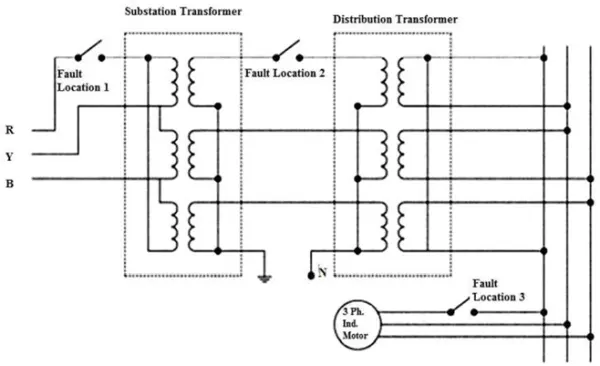
In Figure 1, among the three fault locations depicted, the most critical scenario arises when a phase opens at either the distribution transformer or the substation transformer. During this occurrence, the current surges to nearly ten times the nominal value, while the shaft output power diminishes significantly. If any overload protective device is implemented to disconnect the motor from the main supply during single phasing, subsequent attempts to restart under the same condition result in the motor drawing locked rotor current, surpassing normal rated current by 6-8 times and potentially causing permanent damage. Single phasing poses greater risks compared to voltage unbalance [8].
In situations where faults arise at the substation or distribution transformer, the third phase of the motor draws negative sequence current, with torque being generated by the remaining two phases. The windings of the faulted phases act as generators, producing voltages nearly equal to line voltage. High currents during such occurrences can harm winding insulation and voltage sensing protective devices.
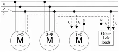
As illustrated in Figure 2, two three-phase induction motors are linked to the three-phase line, along with various single-phase loads. When single phasing occurs anywhere other than at the motor terminals, the faulted phase receives voltage generated by the other two phases due to their interconnected nature. Negative sequence current flows in the third phase, and the generated voltage closely matches the line voltage but is out of phase. This discrepancy can be detected by phase measurement devices. Consequently, if protection devices rely solely on voltage magnitude sensing, they may fail to trip the circuit. Consequently, as depicted in Figure 2, other loads connected to the same phase draw current through the motor winding, leading to a significant current surge in all three motor windings, potentially damaging them. Protective devices intended for single-phase loads, which rely on voltage and current sensing, may not activate if the fault originates at the substation or distribution transformer, as the current required by the load is drawn from the motor, maintaining voltage at nominal levels. Thus, protective devices based on voltage and current sensing for single-phase loads prove ineffective in such scenarios [9].
If any single phasing fault emerges at any of these three fault locations—motor terminals, substation end, or distribution transformer—the current profile will inevitably alter. Consequently, employing both current sensing and voltage sensing devices offers superior protection. In the event of a single line-to-ground fault at the primary of a star-star transformer, the secondary windings manifest the single phasing condition. Conversely, in the case of a delta-star transformer, a line-to-ground fault on the primary manifests as unbalanced voltages across the secondary in all three phases. Therefore, voltage sensing devices can effectively detect single phasing in star-star transformer configurations but may prove ineffective in delta-star connections. When single phasing occurs during motor operation, stator current surges by two to three times while shaft output decreases to approximately 70 percent.
A. Unbalance voltages and frequency
Unbalanced voltage occurs when the magnitudes of the three-phase voltages differ or when the phasor difference deviates from 120 degrees. As per the NEMA MG1-2009 standard, allowable variations for voltage and frequency are within +10% and +5%, respectively [12]. However, the NEMA MG1 guidelines caution against more than 5% unbalance in phase voltage [4]. Such imbalance adversely impacts the insulation lifespan of windings, reduces efficiency, increases losses, and elevates temperatures within the motor.
-
- Definitions of Unbalance voltages:
Asper NEMAandIEEE guidelinesthevoltageunbalancecanbedefinedas:
VoltageUnbalance%age=Maximumdeviationofvoltagefromaverage voltage
Averagevoltage
Asper NEMAguidelines the voltages are line voltages while IEEE guidelines use the phase voltages. It may be seen that both guidelines does not mention the phase angle between the voltages [5]. The reason may be to remove the complexity in the calculations [4].
Positivesequencevoltageandnegativesequencevoltagecanbecalculatedby[4]:
Va
Vp =
3
Va
Vn =
3
Where a =-0.5 +j0.866and a2=-0.5-j0.866
During the unbalanced condition we have to consider the positive sequence current and the negative sequence current. Thepositive sequence current is sameasthe normalrunning conditionofthethreephase inductionmotor butthe negative sequence current arises due to unbalanced voltages. The negative sequence current produces reverse field.
AnotherdefinitionofvoltageunbalancebytheIECisasfollows:
NegativeSequenceVoltage
VUFVUF= x100%
PositiveSequenceVoltage
- Derating of motor during voltage unbalance:
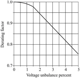
In cases of supply voltage imbalance, as per NEMA guidelines, motor derating is necessary due to the introduction of negative sequence currents, resulting in elevated winding temperatures. Maintaining the same load on the motor necessitates an increase in motor current beyond the rated value to generate the rated torque. Figure 3 illustrates the extent of motor derating relative to the percentage imbalance of the supply voltage. Additionally, NEMA provides a derating chart for overvoltage scenarios [13]. For instance, for a 90% undervoltage condition, the derating factor should be 0.92 [4].
- Effect of voltage unbalance on power factor and efficiency of motor:
Voltage imbalance also impacts the power factor and efficiency of induction motors. An increase in voltage leads to a decrease in power factor and an increase in efficiency. However, the efficiency indicated on the nameplate remains higher regardless of whether the situation involves under or overvoltage. Efficiency declines rapidly in the case of three-phase undervoltage. Installing capacitors to enhance power factor under balanced conditions can exacerbate voltage unbalance under unbalanced conditions [6]. There’s a significant rise in motor temperature due to undervoltage in all three phases compared to overvoltage and normal rated voltage.
A. Overloading effects:
Exceeding the rated capacity of a three-phase induction motor can lead to localized heating within its windings, potentially surpassing the motor’s thermal thresholds. Time plays a crucial role in dissipating this heat. Induction motors possess substantial heat storage capabilities within their core, conductors, and structural mass. During brief periods of overloading or locked rotor conditions, a significant amount of heat becomes trapped within the motor windings, unable to dissipate to other components within the short timeframe, thus causing damage [12]. According to the NEMA MG1 Standard, the stator current of an induction motor should withstand 1.5 times the rated current for a minimum duration of 2 minutes [13]. If the motor is intended for operation in systems with different frequencies, its horsepower and voltage ratings should be adjusted based on the volts per hertz ratio of the specific system. The motor should be designed to withstand locked rotor currents for up to 12 seconds. The National Electric Code (NEC) (NFPA 70-2011) specifies trip thresholds at 125% of the rated current for continuously rated motors. Various NEMA designs exist, tailored to factors such as speed, voltage, horsepower rating, and service factor, particularly for low and medium voltage motors.
A. Maintenance, environmental and manufacturing effects :
- Ventillation effects:
Adequate ventilation is essential to ensure the efficient functioning of the motor, as any obstruction or partial blockage in the ventilation system can lead to a rise in motor temperature. Even a slight blockage in ventilation can result in damage to a small motor. Implementing devices such as airflow detectors or temperature sensors can assist in detecting inadequate ventilation and thus safeguard the motor from potential harm.
- Manufacturing effects:
The global nature of manufacturing and machine sales has intensified competition among manufacturers, compelling designers to seek cost reductions. However, this drive to lower costs has had adverse effects on machine longevity. The cost-cutting measures have been implemented through various means [7]:
a) Decreasing the cross-sectional area of the conductor.
b) Decreasing the thickness of insulation.
c) Decreasing the quantity of steel core material.
d) Innovating rapid manufacturing techniques to lower labor costs.
3.CAPABILITIES OF MICROCONTROLLER ATMEGA32
The ATmega32 microcontroller features 40 pins and operates as an 8-bit device. Of these pins, 32 are designated for data input and output. Its internal frequency is set at 1 MHz, but it can be enhanced to a maximum frequency of 16 MHz through the utilization of a crystal oscillator. The operational voltage range for this microcontroller spans from 4.5V to 5.5V.
A. Data Port
The microcontroller features four data ports, each consisting of eight pins. While all ports can handle data input/output operations, they are limited to reading or writing either 5V or 0V. Only the ADC port has the capability to read voltage levels ranging from 0V to 5V.
A. ADC Port
The digital output boasts a 10-bit resolution, enabling it to detect changes as small as 5mV. For lower resolution requirements, the ADC port proves useful. The microcontroller can only process one ADC pin at a time, sampling and holding the analog input of the first pin until conversion into digital output is complete, after which it proceeds to read the next pin. Its internal frequency of 1 MHz is ample for effectively reading all eight inputs.
A. Arithmetic Logic Unit
The Arithmetic Logic Unit (ALU) can be classified into three main categories: arithmetic, logic, and bit-functions. It facilitates both signed and unsigned multiplications, along with various other arithmetic mathematical operations.
4.PROTECTION OF THREE PHASE INDUCTION MOTOR USING MICROCONTROLLER ATMEGA32
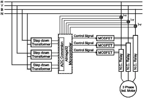
The effective and cost-efficient protection of three-phase induction motors can be achieved through the utilization of the ATmega32 microcontroller. By employing its built-in analog-to-digital converter (ADC), eight analog voltage inputs are seamlessly converted into digital values within the microcontroller itself, eliminating the need for an external ADC converter. This integration streamlines the protection process, as ADC conversion, comparison, and decision-making occur internally, enhancing reliability. Instantaneous phase voltages and phase currents are provided to the microcontroller through step-down transformers and I-V converters, respectively. This comprehensive approach shields the motor from under-voltage, over-voltage, unbalanced voltage, over-current, and single-phasing events. The microcontroller continuously samples these values, compares them with preset reference values, and executes appropriate protective actions. The schematic block diagram illustrating this functionality is depicted in Figure 4.
A. Step down transformer unit
For measuring phase voltages, three 240V/6V center-tapped step-down transformers have been employed. A center-tapped rectifier circuit is utilized to rectify the low voltage signal, with capacitors employed to mitigate ripples in the DC output. To discharge the capacitor, a resistor is placed in parallel within the circuit. The output is calibrated across a potentiometer to suit the microcontroller’s requirements. Variations in the microcontroller’s DC input are directly proportional to fluctuations in the supply voltage. Since normal power system fluctuations may persist for a few cycles without necessitating motor tripping [11], the resistor value across the capacitor is chosen accordingly. Three such setups are implemented for the three phases of the motor’s power supply. The schematic diagram of the step-down transformer unit is depicted in Figure 5.
B. i-v converter unit
The protection against overcurrent for a three-phase induction motor is achieved by employing three individual i-v converters, each rated at 20A/20V for respective phases. The conductors from the motor’s supply terminals serve as primaries for these converters. During motor operation, magnetic flux generated around the phase conductors induces voltage on the secondary side of the converters. This induced voltage is then fed into the microcontroller via the ADC port. To ensure accuracy, these voltages are calibrated against the rated current value and programmed into the microcontroller during normal motor operation. Given that the starting current of the motor typically ranges from 6 to 8 times higher than during running conditions [13], a time delay mechanism is incorporated. The delay duration can be adjusted based on the specific motor type. Additionally, the output of the i-v converter increases proportionally with the motor’s current flow.
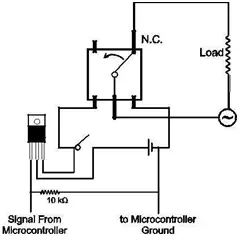
C. Relay unit with MOSFET
Working of Relay : The relays utilized in this protection setup are designed to handle a maximum current of 7A at 300V AC. A minimum voltage of 6V is required to activate the relay. These relays are connected in parallel with the battery, and a single MOSFET is positioned between them. Upon receiving a high signal from the microcontroller, the MOSFET activates, providing power to the relay for its operation. The relays are normally closed, and they interrupt the circuit when energized. All three relays are interconnected across the three phases in the same configuration for consistent operation. To bolster the reliability of the entire protection system, all MOSFETs receive the high signal from the same microcontroller pin.
Working of MOSFET : The microcontroller lacks the necessary power to activate the relay directly. Therefore, a MOSFET serves as a controlled switch to energize the relay, necessitating the use of a separate DC source. Additionally, this approach enables the control of higher-rated relays using the same circuitry, enhancing the versatility of the protection system across a range of three-phase induction motor ratings.
Battery : In this operation, a battery is necessary to supply power to the relays. Since the relays are normally closed, continuous power from the battery is unnecessary. However, in the event of a fault, power will be drawn from the battery to activate the relay. The capacity of the battery, measured in ampere-hours (Ah), is chosen based on the power demand of the relay. Rechargeable batteries offer a viable option, allowing for battery replacement while the motor is running without disrupting the entire protection system. Alternatively, batteries connected to a rectifier system can also be utilized.
Working of relay with MOSFET : The voltage and current values are sourced from the voltage transformer and the current-voltage (i-v) converter, respectively. These readings are fed into the ADC port of the microcontroller for processing. The microcontroller then converts these analog inputs into calibrated digital values. Subsequently, it compares these values against predefined limits. If any value exceeds the specified limit, the corresponding MOSFET will receive power after a designated delay period as dictated by NEMA MG1 standards or as required by the consumer. In instances of voltage imbalance, under or overvoltage in any phase, or overcurrent, all three-phase relays will simultaneously open to disconnect the motor from the power supply. Refer to Figure 7 for the schematic diagram.
5. LABOR ATORY SETUP OF PROTECTION SYSTEM
The laboratory setup depicted in Figure 8 features a three-phase induction motor rated at 1HP, equipped with a protection system capable of safeguarding motors of up to 5HP. The system comprises three step-down transformers with a ratio of 220V to 6V and three i-v converters rated at 20A/20V. Additionally, three relays with a capacity of 230V/7A are linked to three MOSFETs, powered by a 9V battery.
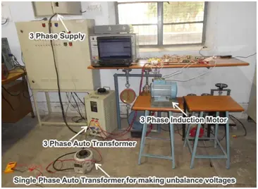
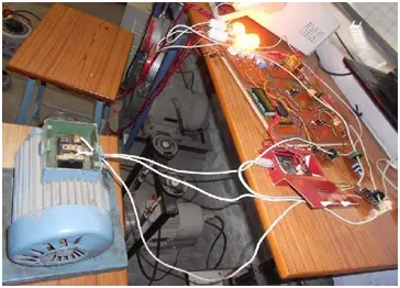
Upgrading to current transformers (CT) and relays capable of handling higher current levels enables the protection system to safeguard motors with higher ratings. Figure 8 provides a detailed examination, while Figure 9 outlines the components comprising the protection system. Bulbs serve as indicators for the three-phase supply provided to the motor.
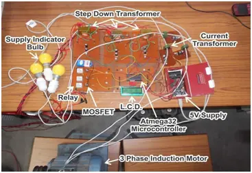
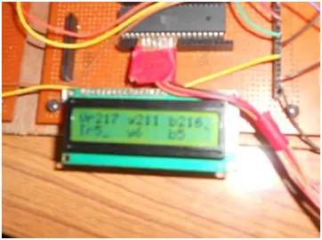
The LCD serves to showcase the digital representations of voltage and current values, as processed by the microcontroller. As depicted in Figure 10, the upper row of the LCD exhibits phase voltages, while the lower row displays phase currents. Should any phase voltage or current exceed its designated threshold, the microcontroller promptly severs the motor’s connection to the power supply. During this action, the LCD indicates zero current alongside the present supply voltages of the three phases. In instances of under/overvoltage, despite discontinuing the motor’s power supply, the microcontroller continuously monitors the voltage and reinstates the supply as soon as it falls within acceptable parameters. In cases of overcurrent, the motor remains disconnected from the power supply for an extended period, though users retain the ability to restart it earlier.
- What microcontroller is used in the protection system?
The system uses the ATmega32 microcontroller. - How are phase voltages measured?
Phase voltages are measured using three center-tapped step-down transformers with rectifier circuits, smoothing capacitors, and calibration potentiometers. - How is overcurrent detected?
Overcurrent is detected via three i-v converters (rated 20A/20V) that feed proportional voltages into the microcontroller ADC. - How does the system disconnect the motor during a fault?
The microcontroller energizes MOSFET-driven relays which open all three phases simultaneously to disconnect the motor. - Can this design be scaled for larger motors?
Yes; scalability is achieved by replacing i-v converters and relays with appropriately rated CTs and relays. - What role does the LCD play?
The LCD displays the digital phase voltages on the top row and phase currents on the bottom row as read by the microcontroller. - Is there a time delay for motor starting current?
Yes; a time delay mechanism is incorporated to tolerate high starting currents (typically 6–8 times rated) before tripping. - What powers the relays when a fault occurs?
A battery (9V in the lab) supplies power to the relays when the MOSFETs are driven by the microcontroller. - Does the protection act on voltage unbalance only?
No; the system uses both voltage and current sensing to detect single phasing, unbalance, under/overvoltage, and overcurrent.