
Summary of BUILDING AN EXTREMELY HIGH POWERED 1-12V LAB POWER SUPPLY ON THE CHEAP
This article details a project to build a high-power lab power supply using refurbished Power-One FNP850 switching units. The author created an adapter board with an AVR microcontroller to control voltage and convert the proprietary connector to standard Molex Mini-Fit Sr. The design supports master/slave configurations, features an LCD display for voltage and current monitoring, and utilizes an all-through-hole PCB layout.
Parts used in the High Powered Lab Power Supply:
- Power-One FNP850-S151G switching power supply unit
- AVR microcontroller
- All through-hole PCB
- 8×2 LCD display
- Molex Mini-Fit Sr 4 position connector
- FCI PwrBlade connector (adapted)
- Grounding contacts built into chassis
For a number of years now I’ve had a couple of high powered switching power supply units made by Power-One. They’re typically found in I.T. equipment and provide a single output rail of either 12 V or 48 V with a very high current rating.
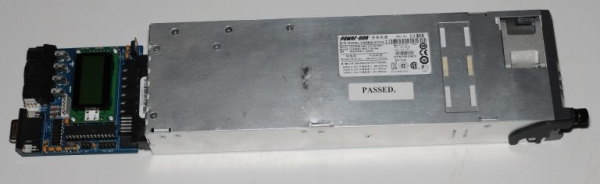
The other cool thing is that in the case of the 12 V model – the output voltage can be changed in software from 1 V to 12 V (12.45 V is the max). The 48 V model does not allow configuration of the output voltage frustratingly.
While they’re very flexible and provide a tremendous amount of current – they’re not so straight forward to hook up to other things.
In this series there are 3 main models:
- FNP600 – Available as 12 V (51 A) or 48 V (12.6 A)
- FNP850 – Available as 12V (69.5 / 73 A) only
- FNP1000 – Available as 48 V (21 A) only
Some time ago I built the above adapter board, which has a small PIC microcontroller allowing me to change the voltage, and also adapt that obscure FCI PwrBlade connector to something easier to deal with – in this case Molex Minit-Fit Sr.
Recently I was prowling eBay looking for the FNP850 model (which I didn’t originally possess) – and – whoa! there’s craploads of them for sale, very cheaply. I picked up a couple of FNP850’s for £15 each free shipping – quite a deal when these originally sold for about 30 times that!
The model which is most plentiful is the FNP850-S151G (12 V 69.5 A) which appears to be a customised version of the original FNP850-12RG (12 V 73 A). The only differences the S151G has from the original 12RG model is the S151G has some extra grounding contacts built into the chassis, it’s been de-rated a little and does not have variable fan speed – it’s at 100% all the time annoyingly.
My discovery that these things are so cheap and plentiful has become the basis of this project – essentially I’ve cleaned up my original implementation for the PIC microcontroller, ported it to AVR – because nobody likes expensive compilers, and released it on Github. I’ve also designed a proper PCB for it.
Design
The board is an all through-hole design the same width of the power supply units. I’ve added an 8×2 LCD which shows the current either configured or measured output voltage, and the output current (the sum between all units when multiple are connected).
The board can be built either as a master or as a slave.
The output connector on my boards is a 4 position Mini-Fit Sr connector however if this is not suitable there is also a couple of 5mm holes under that connector which could be used to bolt cables directly onto the PCB.
Read more: BUILDING AN EXTREMELY HIGH POWERED 1-12V LAB POWER SUPPLY ON THE CHEAP
- Can the output voltage be changed on the FNP850 model?
Yes, the output voltage can be changed in software from 1 V to 12 V. - What is the maximum output voltage for the 12 V model?
The maximum output voltage is 12.45 V. - Does the FNP850-S151G model support variable fan speed?
No, the fan runs at 100% all the time. - How does the new PCB differ from the original implementation?
The new design uses an AVR microcontroller instead of a PIC and includes a proper PCB. - What information does the LCD display show?
The LCD shows the configured or measured output voltage and the total output current. - Can the board operate as both a master and a slave?
Yes, the board can be built either as a master or as a slave. - What alternative connection method is available if the Mini-Fit Sr is not suitable?
There are two 5mm holes under the connector to bolt cables directly onto the PCB.
