Conventionally, wireless controlled robots uses circuits, which have a drawback of limited working range, limited frequency range and limited control. Use of mobile phones for robotic control can overcome these limitations. It provides the advantages of robust control, working range as large as the coverage area of the service provider, no interference with other controllers and up to twelve controls.
Although, the appearance and capabilities of robot vary vastly, all robots share the feature of a mechanical, movables structure under some form of control. The control of robot involves three distant phases: perception, processing, action. Generally, the preceptors are sensors mounted on the robot, processing is done by the on board microcontroller and the task is performed using motors or with some other actuators.
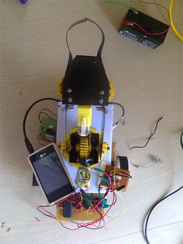
In the project the pick and place robot is controlled by a mobile phone that makes a call to the mobile phone attached to the robot. In the course of a call, if any button is pressed a tone corresponding to the button pressed is heard at the other end called ‘Dual Tone Multiple frequency’ (DTMF) tone. The robot receives these tones with help of phone stacked in the robot. The received tone is processed by the microcontroller with the help of DTMF decoder IC MT8870. These IC sends a signals to the motor driver IC l293d which drives the motor in directions forward, reverse, left, right, pick, release, up, down, rotate left, rotate right.
The important components of this robot are a DTMF decoder, microcontroller and motor driver.A CM8870 series DTMF decoder is used here. All types of the CM8870 series use digital counting techniques to detect and decode all the 16 DTMF tone pairs into a 4-bit code output. The built-in dial tone rejection circuit eliminates the need of pre-filtering.
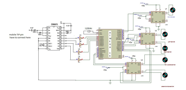
In circuit diagram atmega16 microcontroller pin 9 is connected to push button for reset. Pins 10,30 is connected to vcc +5v and pins no: 11,31 is connected to GND. From DTMF decoder IC m8870 the output pins is connected to NOT gate IC 74LS04. From the NOT gates output is directly connected to atmega16 pins 40,39,38,37.
Input signals are given at PORTA pins 40,39,38,37 differential input configuration is recognized to be effective, the correct 4-bit decode signal of the DTMF tone is transferred to Microcontroller. The pin11 to pin14 of DTMF decoder are connected to the pins of microcontroller (pins 40,39,38,37).
For more detail: Cell Phone Controlled Pick and Place Robot
About The Author
Ibrar Ayyub
I am an experienced technical writer holding a Master's degree in computer science from BZU Multan, Pakistan University. With a background spanning various industries, particularly in home automation and engineering, I have honed my skills in crafting clear and concise content. Proficient in leveraging infographics and diagrams, I strive to simplify complex concepts for readers. My strength lies in thorough research and presenting information in a structured and logical format.
Follow Us:LinkedinTwitter