Summary of Clock Generator With Si5351 and Blue Pill
This article details a DIY clock generator project using a Blue Pill (STM32F103C8) and a Si5351 chip to produce precise squarewave frequencies from 1 mHz to 40 MHz. The author repurposed an old dual-channel oscilloscope, replacing its analog amplifier with digital logic to create two independent output channels controlled via rotary encoders and an ST7735 TFT display.
Parts used in the Clock Generator:
- Si5351 module
- Blue Pill module (STM32F103C8)
- ST7735 TFT display
- 74HC00 (quad nand gate IC)
- Two rotary encoders with switches
- Project box
- Lithium ion battery
- Holtek 7333 low dropout voltage regulator (3.3V)
- Perf-board
- Toggle switch
- Capacitors and resistors
- ST-Link module or Segger J-Link programmer
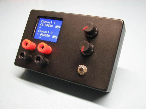
Clock generator
I recently build a pulse generator and it does its job well. It produces pulses of variable length and at several frequencies. But the number of frequencies it can produce is limited and for many jobs the length of a pulse is less important than its frequency. E.g. when you are testing a clock you need a certain frequency, often 32768 Hz, but the pulsewidth (duty cycle) isn’t so important. To address this I made a clock generator, it produces squarewaves of (approx) 50% duty cycle for every frequency.
Library
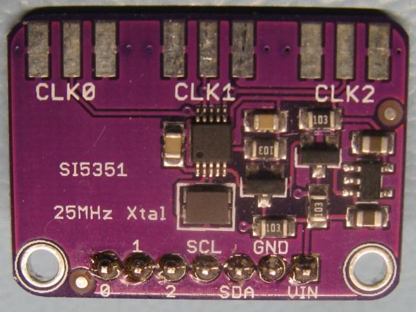
The frequencies are generated with a Si5351 chip from Silicon Labs. This chip can produce frequencies from 4 kHz up to 200 MHz. Usually I read the documentation of a chip and produce the code to use it. But this chip is so complicated that I chose to use a library made by Jason Milldrum, Sebastian Hesselbarth and Rabeeh Khoury. They made an easy to use C-library with one limitation, the lowest frequency you can generate is 1 MHz. I know that there is an extended version of this library for Arduino that starts at 4 kHz, but I didn’t want to use an Arduino. And I’ll tell you why.
No Arduino but a Blue Pill
A few months ago I made a dual channel oscilloscope with a Blue Pill and it worked well. But I never used it as I have a Rigol and a Pico oscilloscope. So it just sat there, gathering dust. Therefore I decided to convert it to something else, and that something else is this project, a clock generator.
Supplies:
Hardware
Si5351 module
Blue Pill module
ST7735 TFT display
74HC00 (quad nand)
2 rotary encoders with switch
Project box
Lithium ion battery
Holtek 7333 (low dropout voltage regulator 3.3V)
Perf-board
Toggle switch
some capacitors and resistors
ST-Link module or Segger J-Link (to program the Blue Pill)
Software
STM32CubeIDE
Si5351 library (made by Jason Milldrum)
MS-Paint (yes really!)
Step 1: High or Low Frequencies
High frequencies aren’t very important for me, I rarely use higher than 8 MHz, low frequencies I do need though. Often lower than the minimum of 4 kHz that the Si5351 can produce by itself. But now I have this library that will make the Si5351 produce frequencies starting at 1 MHz, so they need to be divided. Which is what’s a STM32F103C8 (the microcontroller on a Blue Pill) can do very well with its timers
Two outputs, not three.
The Si5351 has three outputs, the STM32F103 has four TIMERs and with three of these TIMERs it is possible to feed them with external signals. So it is possible to make a generator that produces three independent clock signals. I chose to use just two because it is enough for me and because the dual channel scope I’m converting has two inputs, that I can now use as outputs.
Channels are different
I started off with the idea to have both channels produce a maximum frequency of 1 MHz. While building, that idea changed, now channel 1 goes up to 40 MHz which is probably more than I will ever need.
With hindsight, I should have done this for both channels, but I was afraid that I did’nt have enough room on the pcb (perfboard) for two selectors (74HC00). It would have made the software less messy.
Step 2: Block Diagram and Schematic
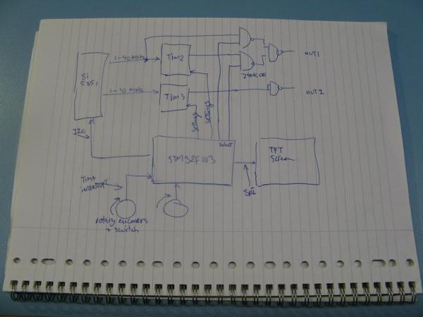
Frequency range
The Si5351 produces frequencies from 1 MHz to 40 MHz for channel 1 and 1 MHz to 10 MHz, for channel 2. That signal is fed to TIMER2 and TIMER3 of the microcontroller. Depending on the selected frequency range it divides this frequency with 10 up to 1,000,000,000 in steps with a factor 10.
So the lowest frequency it can make is with the Si5351 on 1 MHz, divided by 1,000,000,000 is 1 milli Hertz. (one cycle every 1000 seconds) The highest frequency coming from the TIMERs is made with the Si5351 on 10 MHz, divided by 10 is 1 MHz.
Channel 1
For channel 1 there is an extra selector that takes the output of the Si5351 directly, so it skips the microcontroller. This will go from 1 MHz up to 40 MHz. Higher than that doesn’t really work because it is around the maximum of the 74HC gates.
Resolution and precision
There are seven digits you can set, on the 1 MHz to 10 MHz range you can therefore set it to e.g. 1.234 567 MHz with a resolution of 1 Hz. And as this is simply divided to all lower ranges it is also possible to get 1.234 567 Hz with a resolution of 1 uHz (that’s micro Hertz).
(Or even 1.234 567 mHz with a resolution of 1 nHz, although what use such extremely low frequencies have, I don’t know, maybe if you are doing something in geology?)
Oh, do not confuse resolution with precision, the Si5351 uses a 25MHz crystal oscillator that isn’t temperature controlled or temperature compensated. It will change several Hz (parts per million) when the temperature of the crystal changes. As all signals depend on this 25 MHz, they will change with it. But for hobby use its precision is more than adequate. The Si5351 can be tuned to compensate errors, but it doesn’t compensate for temperature changes.
The picture shows 5 kHz measured with a counter locked to a GPS 1PPS signal, after the Si5351 was compensated at 25 degrees Celsius.
Step 3: Hardware
Building the hardware was easy as most of it was already done for the dual channel oscilloscope, the tft screen needed no changes, one rotary encoder was moved a few pins on the STM32F103 because the pins it was connected to are now used for a TIMER, power also remained the same lithium-ion battery and Holtek 7333 low dropout regulator. The Si5351 just needs 3.3v, two wires for I2C and two other wires for the two outputs, so that was easy too.
Most work was the removal of the analog amplifier of the oscilloscope. It needed to go to make place for the 74HC00. The project box needed no changes at all.
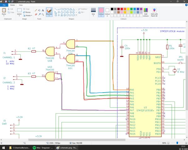
The picture shows part of the schematic in MS-Paint, with colors I paint over the lines with different colours to show with pin connects to which pin. After actually soldering the connections, I press CRTL_Z in MS-Paint to erase them. So MS-Paint DOES have its use after all! 🙂
Three gates of the 74HC00 are used to connect either the Si5351 directly or the TIMER output to the output port of channel 1. And the fourth gate is used as a buffer for the channel 2 port.
Step 4: Software Development and Testing

(It is handy to have the code open in another screen if you want to follow this, for some reason I’m not allowed to upload a zip file with all the code so I will add the most important files to the next step. If you want to get the entire folder I will upload it to google-drive and share it.)
(note to myself, I really should take a look at Github or similar sites)
(EDIT so I setup an account on GitLab and if I did it right you can find the entire project folder in this place)
https://gitlab.com/WilkoL/clock-generator
The code first of all takes care of initialising all peripherals in the STM32F103. GPIO, TIMERs, I2C and SPI, then it enables those peripherals and starts initialising the TFT-screen and Si5351. After that some info is shown on the screen (a small todo is to measure the battery voltage, I might add that later).
The default values are then set and send to the Si5351 and TIMERs of the microcontroller. Now it is ready to start working, which happens inside the never ending “while (1)” loop.
Input This loop checks if the rotary encoders were turned or pressed and if so starts the neccessary actions. The actual reading of the rotary encoders is done inside the interrupt routine of TIMER4. This interrupt is triggered 10000 times a second, it checks the GPIO that the rotary encoders are connected to and does the debouncing of those signals. The pins of the rotary encoders need to be active for 8 times that the interrupt runs (0.8 ms) before they are seen as active. The button needs to be active 16 times (1.6 ms) before it is considered pressed.
The interrupt routine signals the main function with a -1 of the encoder is turned counter clockwise and 1 when clockwise. The button on the encoder just sends a 1 when pressed.
A short explanation of how this works, consider this pseudo code, remember that the interrupt routine is called often, in this case 10,000 times per second.
pseudo code:
volatile uint8_t signal;                         //global variable<br>interrupt_routine()                              //this will be called very often
{
    static uint8_t button;                       //static variable
    button <<= 1;                                //shift one place to the left
    if (physical_button == pressed) button++;    //add a 1 to the left most bit
    if (button == 0xFF) signal = 1;              //when the physical button was pressed
                                                 //at least 8 times in a row send signal
                                                 //to the main program
}
First of all a global variable is needed to be able to send a signal to the main program, the “volatile” keyword means that the program needs to read the content of the variable always, it could have changed at any time (as it does in interrupt routines)
Inside the interrupt routine the variables need to be static, meaning that they are not destroyed when the interrupt routine ends as would happen with normal variables.
The first thing to happen is a shift to the left, so all bits inside the variable move one place to the left making room for a 0 at the end.
Next a check is done to see if the physical button is pressed, if so a 1 is added, changing the 0 at the end into a 1.
If the physical button was not pressed nothing is done, so the 0 at the end stays 0.
The last line checks if all bits in the variable are 1, if so it sets signal to 1, indicating that the physical button indeed was pressed and bouncing was over.
You might notice that signal is never set to 0 in the interrupt routine. This is done by the mail program, after it has handled whatever it should do when the button was pressed.
Shown below are two pictures of actual button presses, as seen on an oscilloscope. You may think you pressed that knob just one, the microcontroller knows better. Take a look at the time-divisions, that second picture shows a bounce that isn’t over after 600 us and you also see that it takes almost 1 ms before it really starts to make contact.
Source: Clock Generator With Si5351 and Blue Pill
- What microcontroller is used in this project?
The STM32F103C8 microcontroller found on the Blue Pill module is used. - How are frequencies below 1 MHz generated?
Frequencies below 1 MHz are created by dividing the 1 MHz minimum signal from the Si5351 using the microcontroller's timers. - Can this device produce three independent clock signals?
No, the author chose to use only two outputs because they were sufficient for their needs and matched the inputs of the converted scope. - What is the maximum frequency for Channel 1?
Channel 1 can produce frequencies up to 40 MHz directly from the Si5351. - Does the Si5351 crystal oscillator compensate for temperature changes?
No, the 25 MHz crystal oscillator is not temperature compensated, so frequency precision changes with temperature. - How does the software handle rotary encoder button debouncing?
The interrupt routine checks if the button signal is active for at least 16 cycles (1.6 ms) before registering a press. - What library was used to control the Si5351 chip?
A C-library made by Jason Milldrum, Sebastian Hesselbarth, and Rabeeh Khoury was used. - Which software environment was used for development?
STM32CubeIDE was used for the software development.