Mission: In 24 hours, develop a wifi-enabled color changing lamp that interacts with various websites to search for established key words and change the color of the lamp accordingly.
Step 1: Gather Materials
- chipKIT WF32 Digilent Microcontroller (1)
- chipKIT Max32 Digilent Microcontroller (1)
- External 5v power supply (1)
- Breadboard connecting wires (20+)
- Resistors (10k ohm (2), 200 ohm (2))
- Photoresistors (2)
- RGB LED strip (1)
- Computer with Internet Access
- MicroUSB cable
- Breadboard
- SG92R Tower Pro Micro-servo (1)
- Wood for house model (any size or design desired)
- Acrylic
- 4 AA batteries
- 4 AA battery holder
Step 2: Code
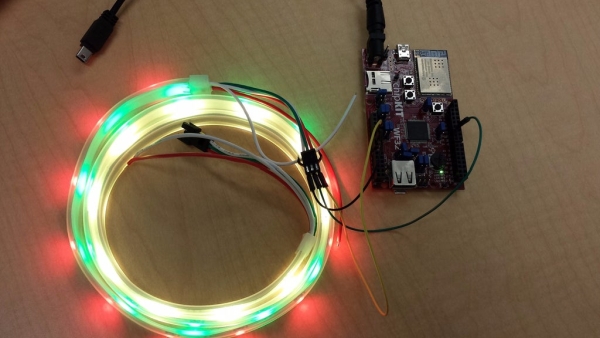
- RGB LED Strip
For powering the RGB LED Strip, “Mpide” software was used to program the chipKIT WF32 Digilent Microcontroller. This software was downloaded following the link described at the end of this step. We then created a new file based on another link described below from “GitHub” to play around with different colors and patterns for the lights on the LED strip. We had to tweak with a few of the parameters on the file to ensure that our specifications would work with our LED strip, but the finished product showed promise for the project as the hue of the LEDs could be changed on command to have multicolored patterns.
Links:
Mpide Software: http://chipkit.net/started/install-chipkit-softwar…
GitHub Code: https://github.com/mwingerson/PICxel
Step 3: Servo Controller
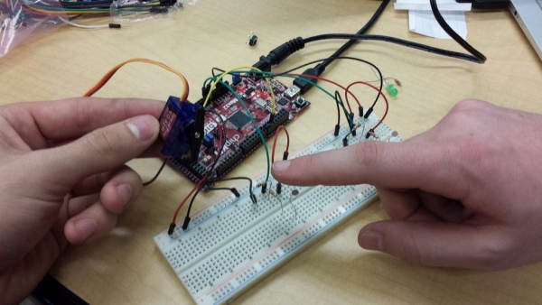
Light Controlled Servo for Model Solar Panel
The LED strip is representative of a lamp inside a modern home, thus an eco-friendly and cost effective way of powering the lamp must be chosen. We decided that a solar panel would be a viable way of powering small electronics. A solar panel could, in theory, be placed on the servo motor which is attached to photoresistors which act like “sun tracking” devices. In this case, a finger can be placed on one resistor and the servo would turn in a given direction and visa-versa. So, when one of the photoresistors had less light hitting it, simulating no sunlight striking the surface, the servo would move in the direction where both photoresistors would have the equal amount of sun hitting them, simulating the optimal orientation for sunlight interaction.This later would be implemented in the roof of our model home.
Step 4: Model House
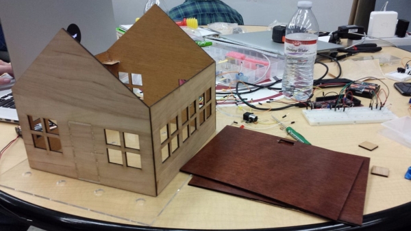
Laser Cut Model House
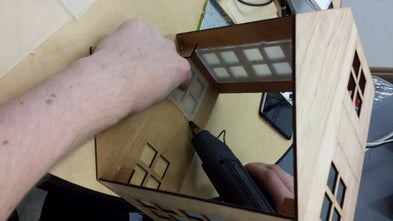
A representative model house was laser cut out of thin plywood and hot-glued into shape. The roof was also laser cut out of a different type of wood with a decorative laminate coating. A port for the servo was cut into one of the sides near the apex of the roof, where it could be displayed as the placement for the model solar panel.
Step 5: Acrylic Windows
Glue in acrylic windows
Acrylic was used as the windows for the model. The acrylic was scrap from our 3D/Laser printing lab, and came in clear form. In order to show more contrast from the lights and hide the wiring, the glass was frosted by running the surface over 220 grit sandpaper until the surface was sufficiently low transparency. The window panes were then hot glued into place.
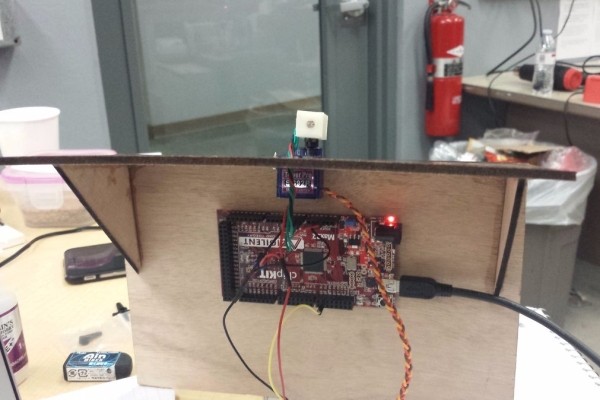
Step 6: Placement of LED Board
Placement of LED board
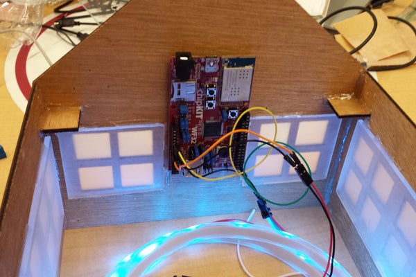
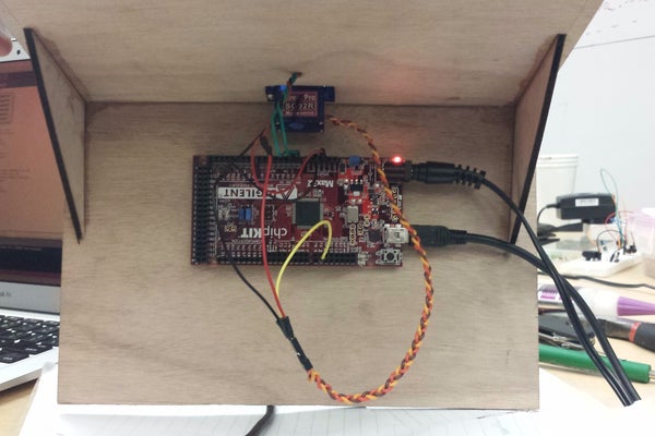
The chipKIT board controlling the LED was placed along the inside-back wall between the window panes. This allowed the wiring to be hidden and provided a neat and tidy placement for wires later in the process. The AA power supply was placed on the opposing end of the model home.
Step 7: Placement of LED Strip
LED strip placed
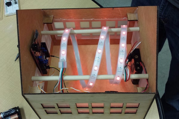
Two wooden dowels were friction fitted in between the front and back of the model which became the support of wrapping the LED strip around. We were looking to get the LEDs suspended in the air and off the ground of the model, this reduced the amount of the LEDs seen through the frosted glass producing a cleaner and more smooth distribution of light.
Step 8: Solar Panel Integration
Integrate the model solar panel system into roof
Once the solar panel and controller board were completed, the system was then mounted on the underside of the roof with the servo extending from the outer surface of the roof. The roof can then be placed and removed easily from the base of the home for ease of access to the controllers and other aspects of the build.
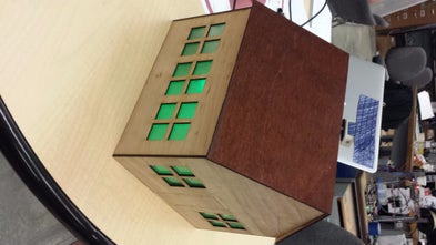
Step 9: Final Product
Source: Color Changing Model House (Hopeful Wifi Connection)