Color TET
- Brief DescriptionThe project is a color “Tetris” based game compatible with NTSC TV.
- Summary and motivationThe project basically utilizes a Mega32 chip, along with a RGB-NTSC converter and a sync generator to produce color on a standard NTSC TV. The code for a “Tetris” type game is then written using the AVR CodeVision C environment.

- The main reason for picking this project was to be able to experiment with color. A laboratory assignment involved using a black&white TV to display a game. However, implementing color was more challenging. It came to our attention that anothe group had done a color based video game in the past year. Hence, we decided to produce a color game on a TV, and eventually decided to clone “Tetris” for sake of simplicity.
High Level Design
Overview
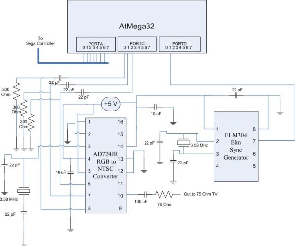
This project consists of two different parts–the hardware and the software. The hardware part consists of connecting the correct inputs and outputs in order to combine the Mega32, the AD724 RGB-NTSC converter, and the ELM304 Sync Generator.
The core of the hardware design is the AD724 RGB-NTSC converter. This chip takes an RGB signal and a composite sync to produce a TV signal that can be recognized by any standard NTSC TV. The RGB input are the 3 bits that are relayed by the Mega32. Since the Mega32 must be able to communicate with the AD724, it must trigger part of its code at the same clock frequency as the AD724. Thus, the AD724 horizontal sync input and the Mega32 interrupt trigger signal is the same signal that is delivered by the ELM304.
The most difficult part of implementing color is to be able to synchronize the software to the vertical and horizontal sync pulses. The software design must be able to detect and distinguish the vertical and horizontal sync signals. Once this is done, the rest of the game code can be implemented using the controls that were implemented by the signal synchronizing portion of the code.
We have chosen to implement 8 colors, with the inclusion of black and white, for simplicity. These 8 colors are merely binary combinations of the 3 color bits. Black represents the background whereas the other colors represent the different pieces in the game.
Hardware Design
Basic Idea
This project consists of two fundamental parts.
The first, and the more time consuming part, is the hardware design. The big problem is –how does one generate color and display it onto the screen? The standard NTSC signal consists of all levels of color, distributed in a fashion that allows the TV to distinguish between them. As visible in the NTSC video signal image below, the video signal is comprised of the beginning of the sync. Once this beginning is seen, a burst of signal is sent, followed by the color. In this case, black corresponds to the lowest voltage level while white is the highest.
It is relatively simple to get a black&white signal since all one has to do is produce a burst and just select high or low logic levels to output with the TV signal. However the color signal is more complicated. Given the timing and memory limits of the chip, it would be rather difficult to produce color. The simple solution is to use a RGB-NTSC converter.
We chose to employ the Analog Devices AD724JR chip for this purpose. The chip uses separate analog and digital power and ground connections (one must remember to use coupling capacitors with both the power inputs, details are in the AD724 data sheet). It also requires a sync signal, which allows it to synchronize itself to the RGB signal. The chip must be given separate horizontal and vertical sync signals. In addition, it has three inputs that correspond to red, green, and blue. This RGB signal is generated by the Mega32 with special timing. Once the chip receives this RGB signal, it combines it with the horizontal and vertical sync pulses to create a NTSC color signal. This signal is relatively high, in terms of ground. Thus, it must be decreased using a capacitor and a resistor so that the TV can differentiate among critical aspects of the video signal. Also, this signal is not a perfect NTSC signal and thus leads to noticeable distortion/wiggle on the screen. The output signal is delivered through a standard RCA video cable to the color TV.
For our purposes, a outside vertical sync signal is not required since our sync generates is able to produce a composite sync. So, the vertical sync input on the AD724 is left high. We chose the Elm Electronics 304 Sync Generator to deliver our sync signal. This chip also requires a coupling capacitor to the power input. It produces an approximate of a 15KHz signal that can be delivered to horizontal sync input of the AD724.
Both the AD724 and the ELM304 run on 3.58MHz clocks. This is required in order to adhere to color video signal generation standards.
The Mega32 is interfaced to the AD724 through PORTC. Three of the pins of this port are designated as red, green, and blue, that serve as inputs to the AD724. The Mega32 runs on a 16MHz clock. Yet, in order to be able to communicate with the AD724, the Mega32 software must also have a 3.58MHz reference. For this purpose, an interrupt was designed to trigger with the ELM304 signal and produce an RGB signal. PORTD is reserved for this interrupt. PORTA of the Mega32 is used to interface with the Sega Genesis serial controller. This port serves as both input and output for the controller where the inputs accept button-press signals and the outputs supply power and ground.
A simple Sega Genesis controller was used to control the game on TV. This controller was chosen over some other controllers on the market since it has no synchronous logic and the buttons simply short connections to give a high or low signal. Low logic signals are interpreted as button pushes. Since we had two controllers, we cut the plug off one of them in order to determine which wires carried the signals for which buttons.
- Other aspects of designInitially, we tried to rely on the previous year’s project’s hardware design. However, since that design was a bit different than that of ours and did include some errors, we decided to base all our design on data sheets and internet resources.There was a lot of confusion regarding the sync signal. According to the AD724 data sheet, the vertical sync input can be held logic high only if a composite sync signal is being provided to the horizontal sync input. However, we were not certain whether the ELM304 provided a true composite signal. Instead of following the suggested design in the ELM304 datasheet, which calls for the use of all ELM304 outputs in order to compose a composite sync, we simply used the first output since it seemed to hold the most information. The other two outputs simply contained other information that was not needed for our project.It is also suggested that the initial design be done on protoboards and not directed soldered onto a prototype board–especially if this is the first time that one is experimenting with color. There is enough room for errors and it is much easier to be able to simply remove a few wires instead of de-soldering them, for debugging.
Software Design - Basic IdeaThe software design is the second part of this project. Although we did not spend nearly as much time on this part when compared to the hardware design; however, this is the most critical part of the design for it allows one the control of where color is displayed on a screen.The game was implemented in steps.The first task was to be able to display color on the screen. So, the very first task was to design the RGB output to the AD724. Since the Mega32 runs on a 16MHz clock and the AD724 is synchronized to a 3.58MHz clock, an interrupt was needed. This interrupt would trigger on the sync signal generated by the ELM304.The idea is to be able to distinguish vertical sync pulses from the horizontal sync pulses. Vertical sync pulses mark the beginning of the screen while horizontal sync pulses iterate over the printable lines on the screen, until the next vertical sync is found.The vertical sync is perhaps the trickiest to detect. The vertical sync is marked distinctively by the sync signal. It looks like an inverted horizontal sync. This signal has pulses that are approximately 5.7us wide. Then the signal stays low for about 20-25us. The trick is to detect this pattern. We employed an external interrupt, namely EXT_INT0 that corresponds to 3rd pin of PORTD (PORTD.2). This interrupt would trigger on the 15KHz signal from the ELM304 chip. To detect the vertical sync pattern, one must count the number of vertical sync pulses, to be sure. Thus, we used a counter that counts at most five vertical sync pulses. Basically, the interrupt is started as being rising edge trigged. Once a vertical sync pulse is found the interrupt is entered on the rising edge, at which time a timer–TCNT0–is reset. Then the interrupt is switched to become falling edge triggered. This is done by modifying bits 0 and 1 of the MCUCR. So, now when the vertical sync pulse ends, the interrupt can detect the falling edge. Meanwhile, the counter was still counting. So, one can compare this counter value to the known width of the vertical sync pulse (~6us). This behavior can be used to detect vertical sync since the horizontal sync pulses are much wider. So, using this technique, one must count about five vertical sync pulses that mark the beginning of the screen.Once the vertical sync is detected, the horizontal sync must be started in order to iterate over the screen. It is apparent that the writable portion of the screen does not include the first 30 lines and the last 10-15 lines (depending upon the size of the interrupt). So once the horizontal line count becomes within range, we can start writing to the screen. This is achieved by simply assigning PORTC to a predefined color. Since there is also a portion to the left of the screen that cannot be visible if written to, there must be a short delay before one can begin writing. The horizontal length of each line depends on the amount of delay encountered since the beginning of the assignment statement to PORTC, until another similar assignment statement with a different color. In our experience, a 1us delay corresponds to about a 3/4 inch line segment on the screen. Once we are done writing to one line, we can exit the interrupt and write another line when the interrupt next enters. One must be careful not to include too many time/memory-intensive calculations within the interrupt. This is neccessary to ensure uniform lines on the screen.
The rest of the interrupt involves TET related code. For our convenience, we decided to define a 10 block x 18 block array that we consider the playable area. Here, the vertical and horizontal dimensions of each TET block are 11 horizontal sync lines and 1us delays, respectively. We have allocated an array of size 200 to represent the screen. Although only 180 elements are written to, the other 20 elements are for debugging purposes for the top and bottom parts of the screen. The interrupt then simply reads each line, or 10 elements of the array, at a time and prints the same data for a period of 11 lines. Then, this line counter is reset and the next “row” of the array can be read and output onto the screen.

The rest of the code defines the TET gameplay. There exist 7 basic shapes in “Tetris”, which, along with their rotated images, constitute about 23 different shapes. We decided to write 23 different code segments to represent each one of these shapes. Each function defines an area where a block will be written to. In addition, it checks and updates information regarding where it is safe to write a block. For example, the block cannot move down, left, or right if there are other blocks present in those locations. Furthermore, since each shape can rotate left and right, each function defines whether it is safe to rotate in either direction, given the current position of the shape as well as the surrounding pieces. Each function takes as its parameters the position to be drawn on the screen (the linear array element), and the direction in which to move. Each function also reserves a color for the specific piece. This works fine since there are 7 pieces and 8 different colors that we can produce with the 3 red, green, and blue bits. The color black is reserved for the background.At the heart of the TET code is a state machine that keeps track of which piece is being drawn and how it is being drawn. As long as the current piece’s function has declared that it is safe to move in a desired position, this state machine re-calls that function with and updated position. It is trivial to move the same type of piece within the screen since the corresponding function has the erase and re-write positions pre-defined. However, it is less trivial to erase and re-write when changing from one type of piece to another. For example, if a T-piece is being rotated, the older T-piece must be erased and the new rotated piece must be drawn. For this, there exists a ‘draw’ flag which lets the corresponding function know whether it must erase or re-draw its designated piece. So while rotating pieces, the state machine switches on the ‘rotate’ variable and determines which piece must be erased with the draw flag and which piece must be drawn with a reset draw flag. The state machine also verifies whether the game is over. Once all pieces have reached the top of the screen array, no more pieces are allowed to fall and the game is considered to be over. In addition, the state machine calls the routine ‘clear_line’ every time a piece lands. This is to check whether a line has been completely filled with color and to erase that line while dropping the rest of the screen down by one line.
The controller interface is managed by the function ‘control’ which checks which buttons are being pressed and modifies the speed, rotatation, and movement variables accordingly.
The pieces drop down the screen at a pre-defined rate, which is much slower than the rate at which ‘control’ is being called. This is to allow the user more freedom with the behavior of the pieces within each falling line. The speed of the game increments linearly as the user clears a certain number of lines.
For more detail: Color Tetris video game