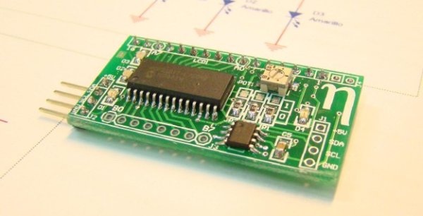
I develop this MCP23017 Brekout Board to interface a 2×16 LCD display with any microcontroller using a standard I2C bus. Typical 2×16 displays needs at least 6 lines to work (when working in 4-byte mode); in some cases, this will be prohibited for some microcontrollers. With this board, you can control it with only two lines (I2C bus) and, by the same price, obtain a few more IO’s. I use the MCP23017 I2C expander as a bridge. This integrated circuit provides 16 IO’s over a standard I2C bus. All the pins can configure as inputs or outputs independently, and supports high speed I2C (up to 1,7MHz). Also, this device has three hardware address pins that allow connecting up to 8 devices in the same bus. The rest of the features can be seen in the datasheet.
- The hardware
The scheme of the board can be downloaded here. In the fist page, there’s the input and output connectors, two LC filters for power supply, a green led to indicate that the board is power and the blocks corresponding to the expander and the LCD connector. Also, you can see R1 and R2, this resistors are the pull-up for the I2C bus. If the bus where you connect it doesn’t have these resistors, you can populated here (1K5 – 4K are admisible values). If the bus already has this resistors (such is my case) then you don’t need to populate it. In the second page, there’s the scheme of the MCP23017 expander. About this page, some tips. Reset pin is at high level (I don’t use it), so the device is always working. Also, the INTA and INTB interrupts are not used, so these pins are not connected. The address direction of the device is configurable by three jumpers in the scheme. With this, you can connect up to eight expanders in the same bus (more about this soon…). In the PCB, I use 0 ohms resistors to configure the address. Port GPA is used as the data bus to the display. Two signals of the GPB port are used to control signals to the LCD, and three more signals (GPB2 – GPB4) are connected to a three general purpose leds that will be usefull in the debug stage. Also, both ports are connected to a general connectors in order to use it as general IO’s if you don’t want to control the LCD. Also, I include an external EEPROM over the same bus. I use the 24LC256 from Microchip, that has a capacity of 32 KBytes. This memory has also three pins to configure the address, so with the same address configuration of the expander, you can configure it, and again you can put up to 8 of these memories in the same bus. At the end, in the last page of the schematic, there’re the two connectors for the GPA and GPB ports, and a stage to control the backlight of the display, if you populated a model that has this feature. This part of the circuit is based on a PNP transistor (BC856) controlled by the GPB5 output of the expander. As I don’t use it, I don’t populate it, not the resistors asociated (R7 – R9).
For more detail: Designing Electronics in Spain

