Introduction
devDuino Sensor Node V 4 is a compact Arduino-compatible microcontroller and is designed to build wireless networks based on transceiver nRF24L01+. You can easily connect other sensors or actuators to this platform, to build your remote monitoring or controlling system. Unlike the version 1,2,3 is on board built-in sensor temperature and humidity.
Model:103990074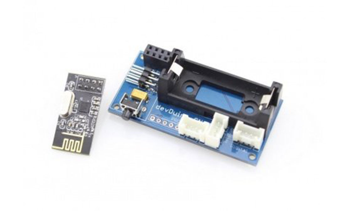
Feature
- Built on Arduino-compatible architecture
- Clock frequency – 16MHz (may be reduced to reduce energy consumption by up to 8MHz)
- Integrated temperature & humidity sensor HTU21D (-40 ° C +125 ° C, accuracy of ± 2 ° C, Relative Humidity: 0-100%, accuracy ± 2%)
- ISP programming interface (recommended)
- Serial programming interface
- Built-in clock button
- Built-in LED green (user configurable)
- 3 GROVE-compatible connector: I2C, Analog, Digital
- Power from one element CR123A (not included)
- Dimensions 30 x 65 mm
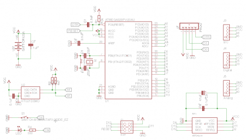
Layout and schematics 
Basic functionality
In the basic version (without additional sensors) module can be used as a wireless sensor temperature and relative humidity (using built-in sensor HTU21D with level control battery (built-in microcontroller).
Expansion Capabilities
Basic functionality can be greatly expanded by connecting the various components GROVE from Seeed Studio.
Interfaces
- A0, A1 – displayed on the terminal “Analog” (the other two pins in the connector – VCC and GND for sensor supply)
- D3, D5 – displayed on connector “Digital” (the other two pins in the connector – VCC and GND for sensor supply)
- A4 (SDA), A5 (SCL) – displayed on connector “I2C” (the other two pins in the connector – VCC and GND for sensor supply)
- Interface for connecting an RF-module nRF24L01 +:
- D11 – RF_MOSI
- D12 – RF_MISO
- D13 – RF_SCK
- D8 – RF_CE
- D7 – RF_CSN
- D2 – RF_IRQ
- D4 – Clock button
- D9 – LED
- HTU21D sensor connected to the bus i2c (pins A4 (SDA), A5 (SCL)).
Features Sensor Node
Module Programming
With the help of programmer based FT232RL (and such)
By default, the standard boot stitched microcontroller Arduino, allowing to record the firmware in the module with the type of programmers FOCA v2.2.
Connecting the programmer via 5-pin (PROG) on the module (battery installed when programming is required – module receives power from the programmer)
Warning! Do not forget to set the programmer working voltage of 3.3V. When flashing the bootloader via ISP, be sure to disconnect the wireless module nRF24L01 +.
Just programmer can be used to debug (monitor port).
Using ISP-Programmer
If you want to get even further about 2K more memory for your sketch, you can use almost any ISP-Programmer for example, Arduino ISP (regular Arduino-compatible board and a standard example of the environment Arduino) or USBtinyISP.
Connecting programmer via 6-pin connector (ISP) on the module (battery installed when programming is required – module receives power from the programmer).
For more detail: DevDuino Sensor Node V4.0 (ATmega 328)