Summary of DISEQC TESTER CIRCUIT WITH ATMEL ATTINY13
This article describes a DiSEqC tester circuit using an Atmel ATtiny13 microcontroller. It verifies DiSEqC 1.0 and 1.1 protocols, checks up to four input ports, and supports variable 22 kHz tone levels for testing under difficult conditions like long feeders. The device features LED indicators for port status, short-circuit protection, and adjustable command frequencies.
Parts used in the DiSEqC Tester Circuit:
- Atmel ATtiny13 microcontroller
- LEDs for monitoring inputs
- 12 V constant tension power source
- Short-circuit protection with current limit
- Sound warning indicator
This device is designed to help define the way DiSEqC-switches to the working protocols 1.0 and 1.1 and the number of entrances to 4 – x. It feeds the unit from the source of… Electronics Projects, DiSEqC Tester Circuit with Atmel ATtiny13 “avr project, microcontroller projects, “
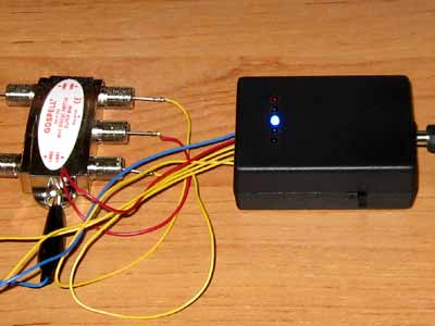
This device is designed to help define the way DiSEqC-switches to the working protocols 1.0 and 1.1 and the number of entrances to 4 – x. It feeds the unit from the source of constant tension 12 V. For monitoring of correct inputs diseka used LEDs, which, if correct diseka must times a second switch, with only one to shine lights at any time. Permanent luminescence or nesvechenie one of the LED will indicate the failure sign. Moreover, it is possible to reduce the amplitude of parcels 22 kHz to 300 mV to test our diseka in difficult circumstances, such as long feeder.
Power supply – 12 V, a maximum of 200 mA
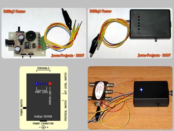
The number of controlled ports – 4, with the help of embedded LEDs
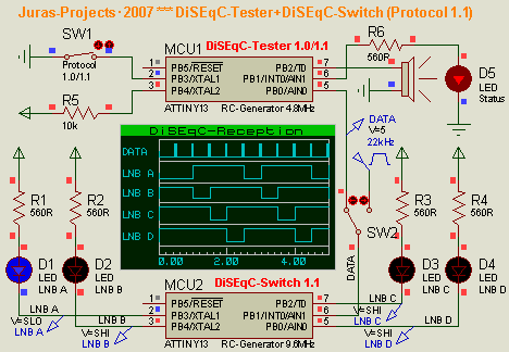
Protocol support DiSEqC 1.0, DiSEqC 1.1 (Write Port Group Commands)
2 22kHz-tone levels – 650mV, 300mV
The frequency of issuing commands – 1 Hz, 2 Hz, switch ports in a circle
Light and sound transmission indication commands
Protection against short circuits (current limit) with light and audible warning
Source: DISEQC TESTER CIRCUIT WITH ATMEL ATTINY13 DiSEqC Tester Circuit with Atmel ATtiny13 schematic hex code alternative link: diseqc-tester-circuit-with-atmel-attiny13.rar
- What protocols does this device support?
The device supports DiSEqC 1.0 and DiSEqC 1.1 protocols including Write Port Group Commands. - How many controlled ports are available?
The circuit controls up to four ports using embedded LEDs. - Can the 22kHz tone amplitude be reduced?
Yes, the amplitude can be reduced from 650mV to 300mV to test in difficult circumstances. - What indicates a failure sign on the LEDs?
Permanent luminescence or non-illumination of one LED indicates a failure sign. - What is the frequency of issuing commands?
The command frequency is set to 1 Hz or 2 Hz with ports switching in a circle. - Does the device have protection against short circuits?
Yes, it includes protection against short circuits with a current limit and light and audible warning.