Summary of DIY ESP8266 ESP-12 Socket – Snap Fit, Breadboard Friendly, No Soldering
The article describes a DIY 3D-printed snap-fit, breadboard-friendly socket for the ESP8266 (ESP-12) that requires no soldering and is made from everyday items. It covers printing settings, step-by-step assembly using bent paper-clip pins, testing with a multimeter, and notes on improving pin thickness for easier breadboard use.
Parts used in the DIY ESP8266 ESP-12 Socket:
- 3D printed ESP8266 (ESP-12) socket model
- 3D printer (Creality Ender 3 V2 used)
- Pliers
- Cutter
- #2 paper clips (straightened into wires)
- Marker (for marking bend positions)
- Multimeter (for continuity testing)
- Optional: 0.6mm copper wire (suggested alternative to paper clips)
I’ve been looking for an ESP8266 (ESP-12) socket for a long time, and the way I see it, It had to have all of these properties:
- 100% Breadboard Friendly
- No soldering required
- Snap Fit and snugly hold the ESP8266
- DIY from everyday household items
- Easy to print
- Easy to build
I found a few solution on Thingiverse.com, But non of them met all my prerequisite, so I designed my own socket.
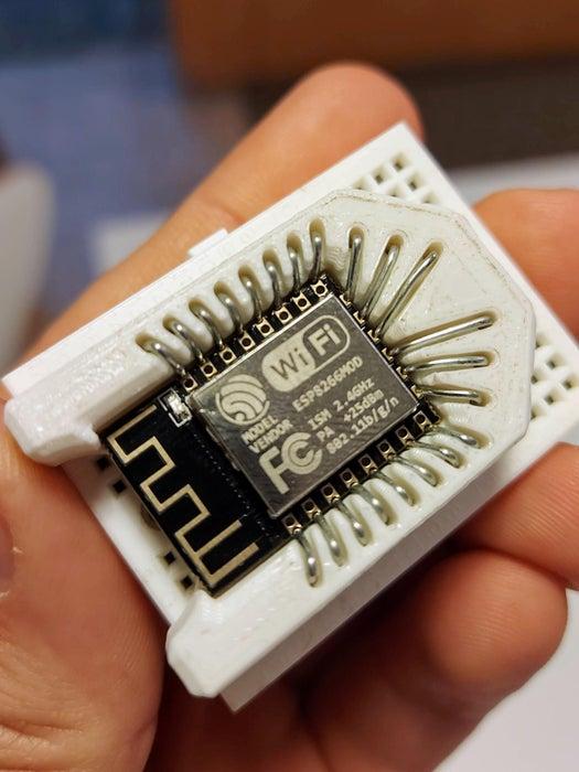
The socket turned out very good and the design met all my expectations and conditions, in addition it has a cool ‘Spaceship‘ look.
Supplies:
- 3D Printer (I used my Creality Ender 3 V2)
- Pliers
- Cutter
- #2 Paper Clips
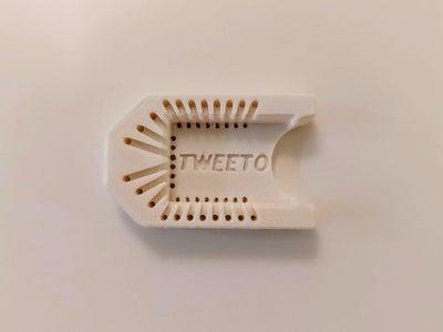
Step 1: 3D Print
I designed the Socket using Autodesk Fusion 360 Personal and I highly recommended it – About 4 hours.
I 3D printed the model using my Creality Ender V2 – About an hour.
Slicing for the Ender 3 V2 was done using Cura with the basic settings, nothing special:
- 20% Infill
- 0.2mm Layer Height
- No Raft
- No Support
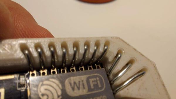
Step 2: Assemble the Pins
My biggest challenge was to make the pins stay in place between uses, while inserting and removing the ESP8266 and while connecting the socket to breadboards, in addition I didn’t want to use glue or more 3D parts (casing and brackets) to keep the pins in place.
After several designs I came up with the solution – a tiny groove at bottom to fix the pin, together with the upper bridge, this design keep the pin in place by countering the upward\downward motion while using with breadboards and fitting the ESP.
The assembly is quite easy and straight forward once you get it, take a look at the animation and the video above to get a better idea.
For each pin:
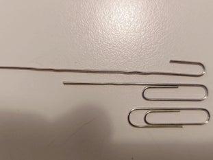
- Open a paper clip to a straight wire
- Insert the wire to the inner hole (the short one)
- Leave enough wire for the bottom grove (don’t bend it yet)
- Bend the upper part, use the top groove as guidance
- Use a marker to mark the outer hole (the long one) position on the wire
- Take out the wire and bend accordingly
- Insert the U shaped wire all the way down
- Flip the socket on a table or a flat surface
- Pull the outer pin to make it flash with the top part
- While pulling the inner pin, bend it half way through toward it’s grove
- Cut any excessive material (Be carful, it can shot out – USE eye protection and pay attention to the cutting direction and projectile)
- Bend it all the way and fix it inside the groove
For ease of assembly, start from the left side, the nose of the ‘spaceship’ and work your way to it’s engines.
Finally, trim all the pins to about 10mm.
Step 3: Quality Check and Usage
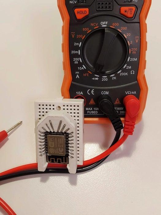
Plug an ESP8266 to the socket and using a multimeter perform a continuity test for each pin, touch the pin with one end and the gold headers on the ESP with the other end, make sure you don’t accidently touching the pin wire.
When you plug the socket to a breadboard, apply force evenly and make sure you press down on the pins for added stability and to keep them from bending out.
My entire motivation for this project was to be able to program the ESP-12 module using a NodeMCU and doing so without any soldering, you can find more about this method here, now I can easily achieve this using my new socket.
Step 4: What’s Next?
The first thing I’ve noticed is that the paper clip wire is a bit thick (0.8mm), I believe using a 0.6mm copper wire will be easier on your breadboard and make it less tight when plugin in the ESP.
I hope I can test it soon and upload my results.
Source: DIY ESP8266 ESP-12 Socket – Snap Fit, Breadboard Friendly, No Soldering
- What are the 3D print settings used?
20% infill, 0.2mm layer height, no raft, no support; sliced in Cura. - How are the electrical pins made?
Paper clips are straightened into wires, bent into a U shape and fitted into inner and outer holes with grooves holding them in place. - Is any soldering required to build the socket?
No, the design is intended to require no soldering. - How is pin retention achieved without glue?
A bottom groove and an upper bridge in the 3D print counter upward and downward motion, holding the bent wire pins in place. - How should I test the assembled socket?
Plug the ESP8266 into the socket and use a multimeter continuity test between each socket pin and the corresponding ESP gold header. - What tools are needed to assemble the socket?
Pliers, a cutter, and a marker are used to shape and trim the paper-clip pins. - How long does printing and designing take?
Designing in Fusion 360 took about 4 hours; printing on an Ender 3 V2 took about 1 hour. - How should the socket be inserted into a breadboard?
Apply even downward force and press on the pins for added stability to prevent bending when plugging into a breadboard. - Can I use a different wire than paper clips?
The author suggests 0.6mm copper wire as a potentially better alternative to the 0.8mm paper clip wire.