Are you bored of your regular displays? Have you got a innovative idea for a game? Have you got a soldering station or somebody to help you with one? Well you are in luck, because with this instructable you will know the basics of the Basys. More precisely this tutorial shall provide a general idea on how you can build your very own POV, that’s Persistence Of Vision, and game in VHDL.
How does a POV work?
Persistence of vision is just a fancy name for optical illusion. It mainly consists out of a strip of LEDs sticked onto a fan blade. The LEDs are programmed to blink or change colors on specific moments, in order to obtain parts of the picture we want to display. Due to the speed of the switching when the propeller is in motion the leds will display the entire picture.
Why use a POV?
Because we can make a nice display with a low budget, because it will be made with your own hands and because it looks cool.
What should I program my game on?
What ever your kind hearth desires and is capable to transmit Bluetooth signals. For this instance we used a Basys3.
What if I can’t do it?
What’s there to be done? Just follow the steps, measure twice and be creative. Heck, it’s so simple, even I can do it.
PS: the project is still under construction, so we will provide updates as the work progresses
Step 1: Hardware Requirements
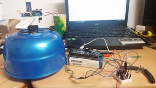
This project consists of two parts: the logic part (on which the game is implemented) and the functional part (the actual POV).
The logic part consists of components received from Digilent:
- Basys3 FPGA board
- PModBT2 – Bluetooth Module for the FPGA
The functional part uses:
- Arduino Nano
- HC-05 Bluetooth Module
- 4-wire PWM controlled computer fan
- 7805 voltage regulator + 2 35V 10uF electrolytic capacitors
- WS2812 addressable RGB LED strip, 144LEDs/m
- a 9V battery
Other tools and accessories:
- hot glue gun
- soldering station
- wires, connectors, PCB boards, pin headers
- cable ties
- a plastic bowl and a plastic ruler (30cm length)
Remark: other hardware may be used, the ones we chose were the most convenient for us.
Step 2: Hardware Implementation
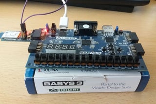
For the logic part, the Bluetooth module is inserted in the Pmod socket A of the FPGA board. The board is also connected to the PWM and Tachometer pins of the fan, in order to provide a speed control (I will come back with updates after its implementation).
For the functional part, we have the electronic and mechanical implementation.
For the electronics, we provided a 9V battery as a supply source. After passing through a voltage regulator, the regulated 5V will supply the LEDs, the Arduino and the Bluetooth module. WARNING: a LED at full power consumes 60mA. If possible, try not to light too many LEDs at the same time (or do it at lower power), as the 7805 provides a maximum of 1A, otherwise there may not be enough power for the Arduino.
The Arduino and Bluetooth module are mounted on a custom-made PCB, with connectors and pin headers used for convenience.
For the mechanical part, we “transformed” a computer fan into a… ruler fan. On the ruler we mounted the electronics using a hot glue gun. Take care, as the ruler has to have the center of mass close to the center of rotation, else strong vibrations will occur. This can be tweaked by gluing counterweights.
Step 3: Logic Part Software
Using the Vivado IDE, we implemented a simple snake game in VHDL. The snake moves around using the buttons on the Basys. As it eats the food, it increases in size. When hitting the edge, the snake will come back from the other side. If it hits itself, it’s game over.
The positions of the snake body and the food are transmitted via Bluetooth to the Arduino. Therefore, the baud rate of both modules must have the same value (9600 in this case). Jumper 4 on the PmodBT will be shorted to ensure this. The module will also work as a slave (awaiting connections), with the HC-05 being the master (actively connect to the slave).
In parallel, the motor control is also implemented (not just yet, I’ll provide updates after we finish working on it). The Tachometer provides 2 signals per rotation. By measuring the time between each signal, one is able to find the rotational speed. Modifying the PWM duty ratio, one is able to obtain a constant velocity of the motor.
Step 4: Functional Part Software
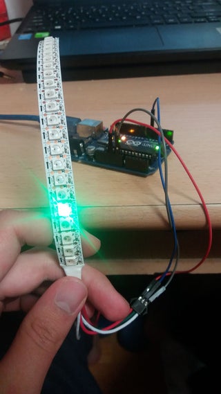
As the LEDs spin, they must be turned on and off such that an optical illusion occurs, and the viewer has the impression that he looks at a static image. Arduino receives via Bluetooth the positions of the snake body and the food and decodes the data (resulting in a number between 1 and board size squared).
The HC-05 has to be set into the Master mode, in order to automatically connect to the PmodBT module. The instructions on how to do this is described in depth here. Note that the baud rate has to be set to 9600 (same as the FPGA Bluetooth module).
Next, a mapping is done : each square in the original grid corresponds to a LED (magnitude) and fan position (phase). For simplicity, we used a polar grid, as seen in the above picture. In order to ensure that the fan is in the correct position when blinking a LED, we issued interrupts every PERIOD/SIZE milliseconds, where PERIOD is the rotation period of the fan (because of the motor controller, this is more or less constant) and SIZE is the desired board size (for simplicity, we considered it square – a 21×21 grid).
For controlling the LEDs, we used the Adafruit NeoPixel library (which can be found in the Arduino Library Manager or on Github).
Source: DIY Persistence of Vision Game Display