Hi all!
I’m very busy last months working on new boards and projects, sorry for the delay!
Some months ago I review the DSETA board due the obsolescence of the microcontroller. I use this board in some projects succesfully. But when I try to manufacture a batch of this boards, I found that the microcontroller (AT89C51RE2) was obsolete. So, the board needs an update to change the microcontroller and maintain most of the features that it has. Now that Microchip buys Atmel, obsoles
cence and samples will not be a problem.
To replace the RE2 microcontroller, I choose one very similar, the AT89C51ED2 microcontroller. Mainly because it shares most of features with the old one and footprint and pinout is almost the same, so replacement is relatively easy to do.
Come in and you can see the new board features, changes and more!!
- HARDWARE
This board is an updated of the previous one, due obsolescence of the microcontroller I use in the past. The main differences between AT89C51RE2 and AT89C51ED2 version are the following ones:
- RE2 has 128K bytes On-chip Flash while ED2 has 64k bytes
- RE2 has On-chip 8192 bytes Expanded RAM while ED2 has 1792 bytes.
- ED2 has On-chip 2048 Bytes EEPROM Block for Data Storage. RE2 don’t have internal EEPROM.
- RE2 has Two Full Duplex Enhanced UART while ED2 has only One UART.
The main difference is on memory size (RE2 has much more of both Flash and RAM) and the second hardware UART. The rest of the features are the same (power supply, IO ports, clock speed…..). So, the replacement is easy and mainly not traumatic.
The scheme of the board is here: EEL_DSETA_V1.2A. You can compare with the old one to see the differences:
- The new board hasn’t the jumpers for choosing the programming serial port. The RE2 version allows to program the microcontroller with a dedicated serial port, while in the ED2 version this port doesn’t exist.
- The J1 connector, used for extend the IO pins of the microcontroller, now has two free pins, due the loss of the second UART.
- The auto-ISP function dissapears, also the buffers and signals that allow it. Now entering in programming mode is done with two pushbuttons (RST and PSEN).
- New board has an extra connector, J3, to connect an external temperature sensor (DS18B20 or similar).
These are the differences on the schemati side. On the PCB design, there’s also some modifications:
- PCB has the same size, holes and connector position. This allows change the old board with the new one without any problem, either mechanical or electrical.
- Jumpers for choosing programming port are eliminated. In the place where they’re, now is the connector for temperature sensor.
- The RST and PSEN buttons are now on the Top Layer for easy programming mode access.
- There’s no silkscreen for the components, only for marking pushbuttons and connector identification.
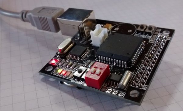
I come back with Seeedstudio PCB manufacturer to order the boards, using their Fusion PCB Service. As always, easy process to ordering, many colours and thickness to choose, good manufacturing and shipping time. And of course, e-test for the boards. Like with the old board, I’m very happy with the result of the boards:
Read more: DSETA board with an AT89C51ED2