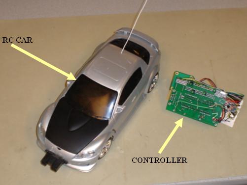
The purpose of this project was to take a traditional remote controlled car and create our own control mechanisms. To control the car, we used a dual-axis accelerometer and LEDs (light emitting diodes) configured as photo-detectors. The control mechanism was selected using a single pole dual throw (spdt) switch was wired in a single pole single throw (spst) configuration. The two-axis accelerometer was used as a tilt sensor that detected how far the chip was angled from its neutral, flat position. An analog voltage was produced for both the x- and y-axes that corresponded to how far the accelerometer was tilted, and in what direction.
A custom LED array was also used to control the car. Though LEDs are traditionally thought of as light producing elements, they also produce a voltage corresponding to how much light they receive brighter environments produce a greater voltage across the LED. We took advantage of this fact by causing the decrease in voltage by blocking light from entering one of the four LEDs (forward, reverse, left and right) to cause the car to move in the appropriate direction (See accelerometer & led sensor array unit).
To implement a safer car, an infrared distance sensor was used to continually scan the area in front of the car. The sensor produced an analog output voltage proportional to how close an object was. When an object was detected, the car momentarily reverses to avoid a collision.
PROJECT OVERVIEW
We chose this project because of our love of cars and the hardware aspect of gadgets. We thought that it would be a novel idea to be able to control the car with one hand by using the dual-axis accelerometer. To provide a contrast to this one-handed approach, we also decided to implement a spin on the traditional two-handed control of the car by using LEDs as photo-detectors. While the use of LEDs would still require two hands, the cost would be even less than the two joystick control scheme that the car came with. We wanted to implement both control schemes, then compare and contrast them at the end.
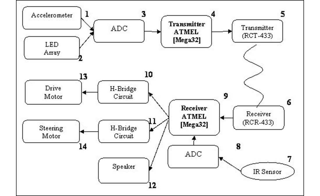 Figure 1: High Level Block Diagram
Figure 1 is a high level overview of our project. This is a very simplified version of the project but gives a general understanding of the main components within the system. For a more detailed analysis see (Hardware & Software Description). The components are used as follows:
1) The MMA6261Q accelerometer drives the car based on how the control unit is tilted by the operator.
Forward tilt drives the car forward
Backward tilt puts the car in reverse
Leftward tilt makes the car turn left
Rightward tilt make the car turn right
No tilt the car does not move
The drive motor and steering motor can be operated simultaneously.
2) The LED sensor array provides an alternate control mechanism by allowing the operator to drive the car by touching one or two of the four LEDs that correspond to forward motion, reverse motion, left turn and right turn.
3) The ADC (analog to digital converter) unit on the Transmitter Mega32 takes the analog voltages from both the tilt sensor and LED touch pad and converts them to a digital number between 0 and 255. The software is calibrated to produce the desired action when a certain value of the ADC output is crossed.
4) The Transmitter Mega32 contains the transfer protocol software which uses the data provided by the ADC to operate the car. The data from it is processed before being sent to the transmitter using the Universal Synchronous and Asynchronous serial Receiver and Transmitter (USART) protocol.
5) The transmitter (RCT-433) takes the information provided by the Transmitter Mega32 and transmits it at 433.92 MHz. The FCC states that any low power non licensed transmitter must not cause interfere with licensed transmitters. The frequency of the transmitter is in the acceptable range of frequencies as listed in Part 15 of the FCC rules. The transmitter used less than 1 milliamp of current when transmitting a logical 0, and about 4.5 milliamps of current when transmitting a logical 1. Because the transmitter transmits a 1 when no signal is inputted, an inverter was used for the input to the transmitter to save power. We do not have to obtain FCC equipment authorization for the circuit that we are building because less than 5 of these circuits will be made and we do not plan on selling them.
6) The receiver (RCR-433), located on the car itself, receives the transmitted signal. The signal has to be inverted to reverse the effects of the inverter on the transmitter end.
7) The IR Sensor detects how far objects are from the front of the car. The unit sends infrared pulses and determines distance by measuring the angle of the beam that returns. A pulse that is reflected from an object that is further away will have a greater angle from the plane of the reflector than an object that is nearby.
8) This ADC (analog to digital converter) converts the signal from the IR sensor into a number in the range of 0-255 to be interpreted by the Receiver Mega32.
9) The Receiver Mega32 contains most of the software for this project. It takes the information that is received, decodes it, checks the output of the digitally converted signal from the IR sensor, and then provides the correct signals to the h-bridges that control the drive motor and the steering servo.
10, 11) The information from the Receiver Mega32 is interpreted as drive forward, reverse, steer left or steer right. The forward and reverse instructions are sent to one h-bridge circuit which is connected to the drive motor of the car. The steering instructions are sent to another h-bridge circuit that is connected to the steering servo motor. A schematic of the H-Bridge and the components used is shown in Figure 11 in the Hardware Design section.
12) The speaker used in this lab emits a sound when the IR sensor senses an object in front of the vehicle when the user attempts to drive forward.
13, 14) The drive motor and steering servo were part of the original car. They both operated at 5V.
HARDWARE DESIGN
Most of the time spent on this project was in designing and building the cars circuitry. The car was gutted except for the chassis, drive motor and steering servo. Even the battery box was modified to accept 9V batteries. The transmitter controls that came with the car were replaced with our custom made controllers. The hardware components for this project were built and grouped accordingly:
Accelerometer and LED Sensor Array
Transmitter Unit
Receiver Unit
Collision Sensing Unit
ACCELEROMETER & LED SENSOR ARRAY UNIT
Freescale MMA6261Q Dual-Axis Accelerometer:
The accelerometer (MMA6261Q) was generously donated to us by Freescale Semiconductor. This unit produced an analog voltage output corresponding to the amount of rotation in the x- or y-plane (the z-axis is referenced vertically). Contained within the device was a surface micromachined capacitive sensing cell. Acceleration along an axis caused a plate to slide, changing the capacitances between the plates (see Figure 4). This change was converted into an analog voltage.
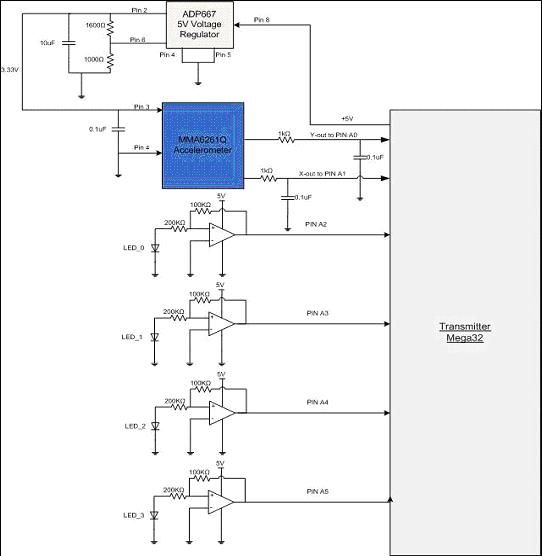
When no tilt was applied in either direction the output voltages of both the x-axis and y-axis was approximately 1.65V. Tilting the sensor forward or backward up to -1g or +1g caused an output voltage between 0.85V and 2.45V, respectively, on the y-axis output line. Tilting the sensor left or right up to -1g or +1g causes an output voltage between 0.85V and 2.45V, respectively, on the x-axis line. These analog voltages were used to determine the threshold conditions at which the commands to operate the car forward, reverse, left, and right were set. We built an RC low-pass filter using a 1 kΩ resistor and a 0.1 μF capacitor (see Figure 5) to filter the outputs of the accelerometer before entering the Transmitter Mega32. This minimized clock noise from the switched capacitor circuit inside the device.
ADP667 Voltage Regulator:
An additional voltage regulator was needed because the accelerometer chip required a voltage of 3.3V, not the 5V that was available on the board. We were able to produce a voltage of 3.3V using an ADP667 5V regulator graciously donated to us by Analog Devices. This chip allowed us to step down the 5V available on the prototype boards by creating the circuit in Figure 6. The values of the resistors were chosen using Equation. 1. VSET = 1.255V (Pin 6), R1 = 1000Ω, R2 = 1600Ω and VOUT was the final output.
4-Button Sensor Array:
This circuit was created using 4 LEDs. The LEDs that were available to us in the lab were yellow, red and green. Through experimentation, we found that green LEDs produced the highest voltages across the terminals from ambient light, and also had the largest voltage decrease when covered, which were desirable characteristics for our application. Through further experimentation, we found that covering the sides of the LEDs with opaque tape while leaving the top exposed produced a greater voltage change when covered up. The voltage change from the LED was small therefore amplification was used to magnify the change for more foolproof detection. To accomplish this, each LED was connected to an LM7111 op-amp in a non-inverting configuration (Fig. 7), which amplified the signal voltage by a gain of Av
This was enough to increase the voltage change while remaining within a maximum of 2.56V, which was the value of the internal voltage reference used by the ADC. The op-amp output for each of the LEDs (LED0 to LED3) was connected to ADC pins on the Transmitter (i.e. Pin A2 to A5). A delay was necessary between successive conversions because each ADC conversion value could take up to 125 microseconds to stabilize. We chose a delay of 1 millisecond to be safe which was still fast enough for our purposes. Each LED controlled specific functions of the car as follows: LED0 moved the car forward; LED1 moved the car backwards; LED2 turned the car left; and LED3 turned the car right. Because it was possible to press both forward the reverse LEDs or both left and right LEDs, code was specifically written to stop the car or drive the car straight, respectively, in these situations
The Transmitter Units circuitry in Figure 8 was essential in sending the wireless signal to the remote controlled car. The transmitter used on/off keying (OOK), where the transmitter sends a logic 1 to transmit a logic one, and turns off to transmit a logic 0. The serial output from PortD.1 of the microcontroller (see Transmitter Software) was first inverted. This was done because the transmitter naturally sends a logic one when no data was inputted, which consumes more power than when the transmitter transmits a logic zero. Since the amount of time that data was being sent was very small, the inverter was used to save power. The inverted signal was then sent to the RCT-433 Transmitter where the signal was radiated through the 18cm antenna. An antenna of 18cm was used because the optimal antenna length was one-fourth of the signal wavelength. A 47 uH inductor was used between the power supply and the transmitter unit to prevent the RF energy from shunting to the power rail, which was an AC ground. A 1 nF capacitor was used between the transmitter and the antenna to prevent detuning of the signal.
The Wireless Protocol written by Meghan Desai was used to transmit data. This was a very convenient protocol to use because the transmitted and received functions were laid out for us. We found some errors in the txrx.c driver file that had to be corrected before use. We also had to make some other slight modifications because we chose to use a baud rate of 1200 bps, which required setting both UBRRL and UBRRH. Even when using a lower baud rate led to less dropped packets, it did not totally eliminate the problem. To further solve this, we decided to send packets of information 5 times a second, so that even if a packet was dropped or corrupted, a new packet would be sent shortly thereafter.
The Receiver Units circuitry in Figure 9 was attached to the remote controlled car. The RCR-433 receiver was matched to the RCT-433 transmitter that we were using. The 1 nF capacitor between the antenna and the receiver unit prevented detuning of the signal. The 47 uH inductor between the power supply rail and the receiver unit prevented the RF signal from shunting to the power rail, which was an AC ground. The received signal was then inverted to reverse the effects of the inverter on the transmitter side. The signal was then sent to PortD.0 of the microcontroller, which was the USART receive port.
The Sharp GP2Y0A02 IR distance sensor operates by transmitting infrared signals and measuring the angle of the beam that returns in relation to the plane of the sensor (see Figure 2). The sensor was mounted to the front bumper of the car and tilted slightly upward to eliminate false readings from ground reflections. The sensor was an analog device that outputted a voltage proportional to how close an object was to the car (see Figure 10). Though the output became erroneous below 15 cm, we did not notice any adverse effects in our testing
The output of the distance sensor was fed into PortA.0 of the ADC on the Receiver Mega32. Whenever an object came closer than 24, a signal was sent to the speaker to emit a tone. The car was then instructed to reverse briefly. Merely telling the car to stop was not suitable because of the cars speed its momentum would still allow its collision.
We had initially tried using a Sharp GP2D12 IR sensor because it was a surplus item that Professor Land had. However, we found that its range of 8 was not large enough to provide the necessary safety features. We needed a larger range because the car was not able to stop very quickly.
Parts List:
|
Items |
Quantity |
Price (per quantity) |
| Atmel Mega32 |
2 |
$8.00 |
| PC board (last years) |
2 |
$2.00 |
| Solder board |
2 |
$2.50 |
| Receiver (RCR-433) |
1 |
$4.00 |
| Transmitter (RCT-433) |
1 |
$4.00 |
| Sensor board w/ accelerometer (MMA6261Q) |
1 |
Donated |
| IR sensor (Sharp GP2Y0A02 IR sensor) |
1 |
$12.50 |
| Voltage regulator (Analog Devices ADP667) |
1 |
Sampled |
| Radio controlled car |
1 |
Already owned |
| 9V battery |
3 |
Already owned |
| LEDs, capacitors, resistors, inductors |
Lab supply |
|
|
TOTAL COST |
$45.50 |
|
For more detail: Dual Control R/C Car Using Atmega32