
Summary of Easy-Downloader V1.1 with SDCC using AT89C2051
The Easy-Downloader V1.1 is a programmer board designed for learning and developing with affordable 20-pin microcontrollers using SDCC firmware. The project features hardware updates, including a MAX232 RS232 level converter and a single diode for polarity protection. The PCB layout was created using OrCAD Layout Plus, offering compact Gerber files for manufacturing. This initiative allows users to design schematics, write code, and lay out boards efficiently.
Parts used in the Easy-Downloader V1.1:
- AT89C2051 (Master chip)
- MAX232 (RS232 level converter)
- Single diode (DC input polarity protection)
- Q2 and Q3 (TO92 plastic package transistors or small signal replacements)
- VB1 (Male type connector)
- Resistors (1/4W or 1/8W 5%)
- Firmware file writer1.hex
Complete schematic, orcad pcb layout of Easy-Downloader V1.1 and modified firmware with sdcc.
I am very happy to use sdcc for writing firmware of my project. The compiled code is very compact and nice. After I succeeded writing a new firmware of xtimer and Easy-downloader V1.1 with sdcc. I cannot stop preparing a new page that gives the idea how to use sdcc and of course it’s time to renovate my old project with orcad. For now I can design the hardware, draw a schematic, write the firmware and layout the pcb. So I think why shouldn’t begin with Easy-Downloader. Since the programmer board will enable learning and developing the small project with a cheap 20-pin MCU easily.
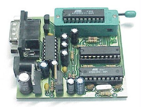
Hardware
The hardware has a bit change at rs232 level converter. Now the circuit uses a popular rs232 level converter, MAX232. Also I cut the bridge diode at the DC input, now I use only one diode to prevent wrong polarity of a given DC adapter.
Layout
The pcb layout was made with orcad Layout Plus. The gerber file is available at download section below. Here I like to show how nice it is. The top and bottom layers are shown in Figure 2 and Figure 3. Figure 4 shows the component placement layout.
Bill Of Materials
The component list is shown in Figure 5. U1 the master chip must be programmed with writer1.hex before the programmer board can run properly. Q2 and Q3 are TO92 plastic package! With a CAN package, pin positions may differ on the layout. You can use any small signal transistors to replace them. VB1 is male type! All resistors can be 1/4W or 1/8W 5%.
For more detail: Easy-Downloader V1.1 with SDCC using AT89C2051
-
What tool is used to write the firmware?
The project uses sdcc to write the firmware, resulting in very compact compiled code. -
Which software was used for the PCB layout?
The pcb layout was made with orcad Layout Plus. -
What component replaced the previous bridge diode at the DC input?
A single diode is now used to prevent wrong polarity of a given DC adapter. -
How can I replace the transistors Q2 and Q3?
You can use any small signal transistors to replace them if you have a CAN package where pin positions may differ. -
What power rating can be used for the resistors?
All resistors can be 1/4W or 1/8W 5%. -
What must be done before the programmer board runs properly?
U1 the master chip must be programmed with writer1.hex before the programmer board can run properly.
