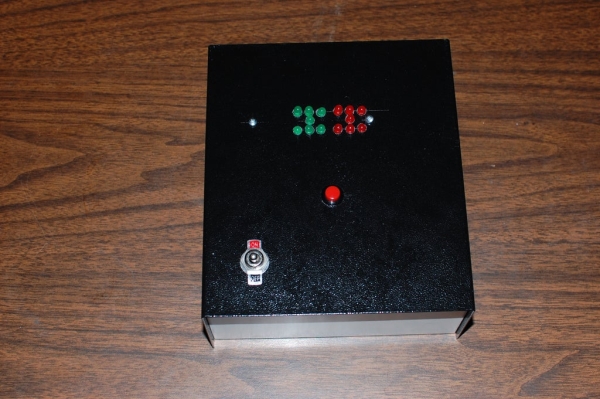
This project is an electronic dice using an Attiny84 chip. The Attiny84 works like an Arduino except it is a 14 pin chip and is has less memory and there is no built in programmer. I will be showing how to upload a program with an Arduino using the Arduino IDE and a USBtinyISP in later steps.
One advantage that the Attiny84 has over the Arduino is the fact that all eight pins on one pin bank (A) are available. If you want to address the pin registers directly or program in assembly language this makes it much easier. I am not using this feature in this project, but I thought I should mention it in case this is your introduction to Attiny84.
For more information on addressing the pin registers directly see this instructable:
https://www.instructables.com/id/Fast-digitalRead-d…
For more information on Atmel assembly language see this collection of instructables:
https://www.instructables.com/id/Command-Line-AVR-T…
You will need:
- Perma-Proto Half-sized PCB – https://www.adafruit.com/products/1609
- 14 pin IC socket – https://www.sparkfun.com/products/7939
- Attiny84 IC chip – https://www.sparkfun.com/products/11232
- 7 Red 5mm LED – https://www.sparkfun.com/products/9590
- 7 Green 5mm LED – https://www.sparkfun.com/products/9592
- 14 Resistors 470-560 Ohm – Purchased locally *
- 22 Gauge solid hookup wire (red, black, green and yellow) – Purchased locally
- Metal case – http://www.jameco.com part #208929
- Pushbutton switch – http://www.jameco.com part #315660
- Toggle switch – http://www.jameco.com part #158060
- 2 #4-40×1 inch machine screws – Purchased locally at Ace Hardware
- 2 Nylon #4-40 nuts – Purchased locally at Ace Hardware
- 2 #4 Nylon spacers 1/2 inch long – Purchased locally at Ace Hardware
- Small wire nut – Purchased locally at Ace Hardware
- Battery Holder – http://www.jameco.com part #216114
- 3 AA batteries
* This resistor kit from Sparkfun has the 470 Ohm resistors you will need for this project, and a lot more.
Step 1: Socket and Cross Wires

This is the pinout diagram for the ATtiny84 chip:
                          ATtiny84
                    VCC - 1  U  14 - Ground
                          2     13 - Arduino Digital Pin O
                          3     12 - Arduino Digital Pin 1
                          4     11 - Arduino Digital Pin 2
  Arduino Digital Pin 8 - 5     10 - Arduino Digital Pin 3
  Arduino Digital Pin 7 - 6      9 - Arduino Digital Pin 4
  Arduino Digital Pin 6 - 7      8 - Arduino Digital Pin 5
Each die is composed of seven LEDs and uses four digital pins, arranged like this:
             Green       Red
              LED        LED
             2 1 0      5 4 3
               7          6
             0 1 2      3 4 5
Mount the IC socket with the alignment notch pointing to the right.
The pink line on the IC is the alignment mark for the IC, it will go on the right when the IC is installed.
Solder the cross wires as shown.
Step 2: Center LEDs
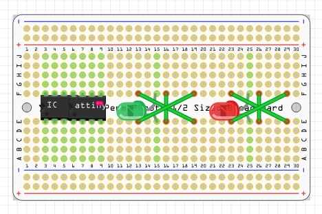
Solder the center LEDs.
Solder the green LED, the anode (long wire) goes in F-15 and the short lead goes in E-15.
Solder the red LED, the anode (long wire) goes in F-25 and the short lead goes in E-25.
The LEDs should stand about 1/4 inch above the board.
Step 3: Resistors
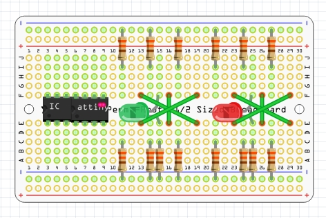
The diagram show the resistors on top in the ground rail and in row I, the resistors on the bottom are in the ground rail and row C. In Fritzing the resistor mounting holes have to be .4 inches apart. Using 1/4 watt resistors it is possible to put them in mounting holes .3 inches apart. The resistors are actually soldered into rows B on the bottom and J on top.
Source: Electronic Dice Using Attiny84