Summary of Embedded Programming
This article details the author's embedded programming journey, starting with adapting Arduino C++ code for an ATtiny44 to toggle LED states via a button. It covers troubleshooting hardware connections and driver installation, followed by implementing similar logic using raw C and Makefiles after installing toolchains. The project expands to control a tri-color LED pattern based on button presses. Finally, the author analyzes the ATMEGA16U2-AU microcontroller datasheet, reviewing its architecture, memory, pinouts, and communication interfaces like SPI and USB for future final projects.
Parts used in the Embedded Programming Project:
- Arduino environment
- ATtiny44 microcontroller board
- USBTinyISP programmer
- LEDs (single and tri-colored)
- Push-button switch
- Cable wires for board connection
- USBtiny driver software
- Atmel GNU Toolchain
- GNU Make
- AVRDUDE utility
- Atom text editor
- ATMEGA16U2-AU microcontroller
1. Programming Board
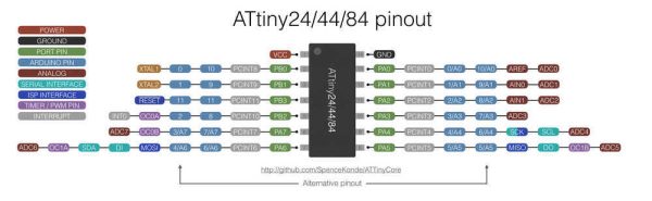
Blinking Code using Arduino environment CODE: I started with code code from Jaclyn Berry's page :const int buttonPin = 7; const int ledPin = 2; int buttonState = 0; void setup() { pinMode(ledPin, OUTPUT); pinMode(buttonPin, INPUT); } void loop() { buttonState = digitalRead(buttonPin); if (buttonState == HIGH){ digitalWrite(ledPin,HIGH); } else{ digitalWrite(ledPin,LOW); } }The key steps to adapting this to my board are pretty simple. All I have to do is change the pins to work with my board and to adjust certain board/programmer settings in the Arduino environment. This diagram shows what the pins are named in the eyes of Arduino vs. what you see on the schematic.
My LED pin is A7 and my switch pin is A2. I changed the code to toggle between blinking or
being a solid light based on the button press.
My final code was this (.ino file linked here):
const int buttonPin = A2; //define button locations
const int ledPin = A7; //define LED location
int buttonState = 0; //button state defined as low to start
int count = 0; //set up a counter to change the LED state
void setup() {
pinMode(ledPin, OUTPUT); //set LED as output
pinMode(buttonPin, INPUT); //set button as an input
}
void loop() {
buttonState = digitalRead(buttonPin); //read state of button
//Blink option:
if (buttonState == HIGH && count ==0){ //if button is off and you're on state1
digitalWrite(ledPin,LOW);
delay(100);
digitalWrite(ledPin,HIGH);
delay(100);
}
//Solid option:
else if (buttonState == HIGH && count ==1){
digitalWrite(ledPin,HIGH);
}
//When button is pressed:
else{
digitalWrite(ledPin,LOW);
count = count +1;
if (count >1){
count=0;
}
else{
}
}
}
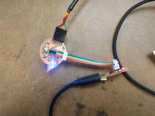
CONNECTING BOARD & PROGRAMMER: For this set up my settings under the Arduino tool menu were: Board: "ATtiny 24/44/84" Processor: "ATtiny44" Programmer: "USBTinyISP" (1) Arduino was not identifying my USBtiny & my programmer didn't seem to be getting powered properly. After trouble shooting for a while I realized one issue was that the connecting cable I made for my board and programmer wasn't working properly. When I got new wires and connected the two boards Arudino was able to find my board! The no longer working cable :'( :
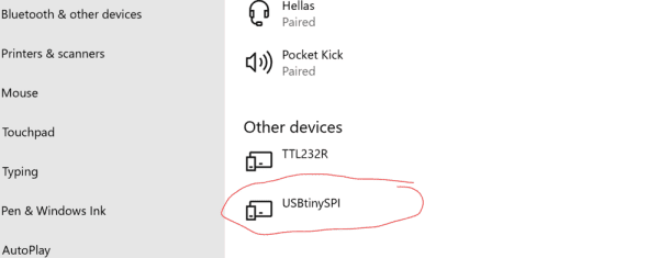
2) Another key issue was that I did not have the driver downloaded for the USBtiny. When I
went to computer connected devices I saw that it said that the driver was "unavailable", so I
had to go online and download a driver- then it worked! love it. Here is what it showed in
my "other devices" once I had the driver:
It successfully uploaded and the button could toggle between blinking the light or keeping it
static!
(2) Blinking Program using C-program & Makefile
I started with Rob Hart's code . This comes with both a C file and a make file. His code turns
on an LED in response to a button press
To adapt it I did the following:
(1) Toggle between a blinking state and a solid state
(2) Changed the pin assignments
Here is the code I wrote:
#include
#define bit_get(p,m) ((p) & (m))
#define bit_set(p,m) ((p) |= (m))
#define bit_clear(p,m) ((p) &= ~(m))
#define BIT(x) (0x01 << (x))
// Button PA5 (pin 8).
// LED PB2 (pin 5).
int main()
{
bit_set(PORTA,BIT(5)); // Turn button pull up resistor on by setting PA5(input) high
bit_set(DDRB,BIT(2)); // Enable output on the LED pin (PB2)
while (1)
{
if(bit_get(PINA,BIT(5))) // Button is up, turn off
bit_clear(PORTB,BIT(2));
else // Button is down, turn on
bit_set(PORTB,BIT(2));
}
}
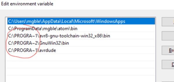
Getting the c-stuff to work on my computer: I followed Julia Ebert's process for uploading C-programs to an Attiny44. ISSUES: (1) At first "make" didn't work. I had to follow the process here (written by Brian) that took me through installing the Atmel GNU Toolchain, installing GNU Make, installing avrdude, and updating my PATH. NOTE ON PATH: I was having issues with my PATHs even after exactly following this process above. When I tested "avr-gcc --version" in my terminal is said command not found. I found this resource that showed me that you sometimes have to write the "Program Files" portion of the path as "PROGRA~1" to fix issues involving the space in the name. It worked! Happy PATHs:
(2) Now make was working and my paths were correct but I kept getting this error.
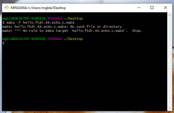
After a lot of trouble shooting I realized that when I was downloading the echo files Windows
was adding a .txt to the end of both files. In Atom I renamed the files and finally the make
function worked, I got my hex file!:
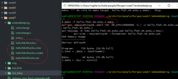
So to review, the process is as follows: (1) Open terminal in directory w/ the C and make file (2) Comile & make hex filemake -f hello.ftdi.44.echo.c.makeNow all I have to do is (3) Send the file to the board:make -f hello.ftdi.44.echo.c.make program-usbtiny(4) Set the clock on the board:make -f hello.ftdi.44.echo.c.make program-usbtiny-fuses~~~~~~change the c and make file names to match the project you care about~~~~~~~~~ Embedded Programming I started to do for my final: I started with Neil's blinking program (written in C). In this program an LED turns on in response to a button being pressed. I want to change it so that a button press makes a string of lights toggle between different color patterns. This will be integrated into my final project in the housing of the UFO buoy. I reconfigured my board to use this tri-colored LED Here is the C-Code I wrote to toggle the color changing LED:// Copied from Rab Hart's code that was... //Shamelessly copied and mofied from Neil Gershenfeld's for purposes of instruction. //This cycles the color pattern of LEDs in response to button press //For the ATTINY44 // Button PA2 (pin 8). // RED PA7 (pin 5). // GREEN PA6 // BLUE PA5 #include < avr/io.h> // this includes all definitions of registers and bits of registers, including pins and port names. #define output(directions,pin) (directions |= pin) // set port direction for output #define input(directions,pin) (directions &= (~pin)) // set port direction for input #define set(port,pin) (port |= pin) // set port pin #define clear(port,pin) (port &= (~pin)) // clear port pin #define pin_test(pins,pin) (pins & pin) // test for port pin #define bit_test(byte,bit) (byte & (1 << bit)) // test for bit set #define input_port PORTA // The button is on port A #define input_direction DDRA // DDRA defines input/output for port A #define input_pin (1 << PA2) // The button is on pin 5 of port A (1<< PA5) = (1<< 5) = 0b00100000 #define input_pins PINA // PINA is the register that is read to detect input high or low. #define output_port PORTA // port B will be used for the LED #define output_direction DDRA // DDRB defines input/output for port B #define output_red (1 << PA7) // #define output_grn (1 << PA6) #define output_blu (1 << PA5) const int i = 0; int main(void) { // // main function. // // initialize pins output(output_direction, output_pin); // set output for LED pin. set(input_port, input_pin); // turn on internal pull-up input(input_direction, input_pin); // set button pin for input. // main loop while (1) { if (pin_test(input_pins,input_pin)) //test button pin. if(i==0){ set(output_port,output_red); i++; } if(i==1){ set(output_port,output_grn); clear(output_port,output_red); i++; } if(i==2){ set(output_port,output_blu); clear(output_port,output_grn); i++; } if(i==3){ set(output_port,output_red); i++; } if(i==4){ set(output_port,output_grn); i++; } if(i==5){ clear(output_port,output_blu); i++; } if(i==6){ clear(output_port,output_red); i++; } if(i==7){ clear(output_port,output_grn); i=0; } else // if button isn't pushed, stay how you are! } }I then did the same program in Arduino: The code I wrote in week 5 (onthe left) and the code I made for this type of blinking.
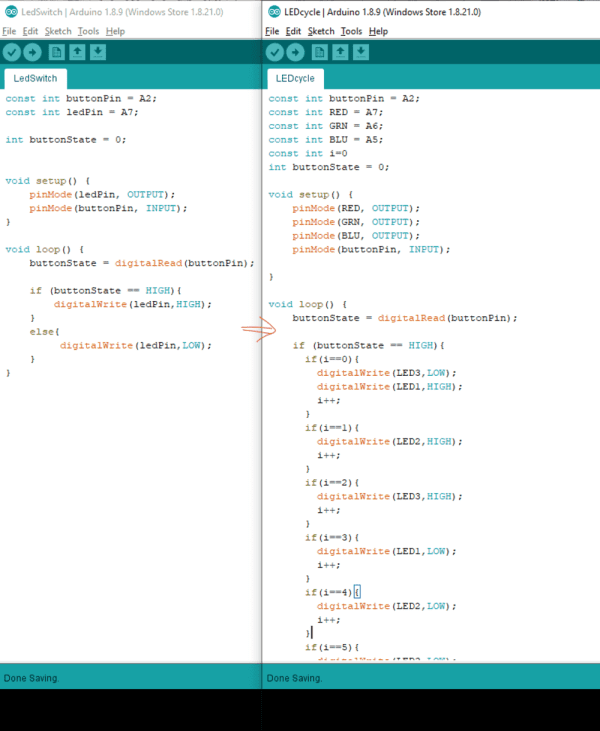
I haven't uploaded these yet before I don't have the board built yet! But it as good practice
in embedded progamming and hopefuly I won't have to change these too much when I have the
board built for them to work.
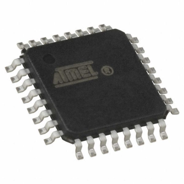
2. Reading Datasheet & prepping final project board
For the programmer this week I used the board I made in week 5, but in my final project I will
be changing my board a lot and switching to the ATMEGA16U microcontroller.
This week I read the datasheet for the ATMEGA16U2-AU. These cost about $2 when you buy in
bulk.
Here is the datasheet for the ATMEGA16U. This is 300+ pages so I've highlighted the key
information here:
The ATMEGA16U
This is an 8-bit AVR microcontroller. This means that all the messages it reads or writes are
8-bits long. AVR is the specific family of microcrollers that this one belongs to. AVR
microcontrollers run on the Harvard architecture system, where  separate memory systems are
used to store instructions and data (Wikipedia page for Harvard Arch).

This is the 16K Byte version, so there are 16K Bytes of In-System Self-Programmable Flash
(ISP Flash).

Here is the block diagram of the microcontroller:
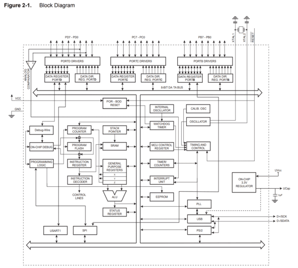
The listed features are:
8K/16K/32K Bytes of In-System Programmable Flash with Read-While-Write capabilities
allows the program memory to be reprogrammed in-system through an SPI serial
interface, by a conventional nonvolatile memory programmer, or by an on-chip Boot program
running on the AVR core
512/512/1024 Bytes EEPROM,
512/512/1024 SRAM,
22 general purpose I/O lines
32 general purpose working registers
two flexible Timer/Counters with compare modes and PWM
one USART
a programmable Watchdog Timer with Internal Oscillator
an SPI serial port
debug WIRE interface (also used for accessing the On-chip Debug system and programming and
five software selectable power saving modes)
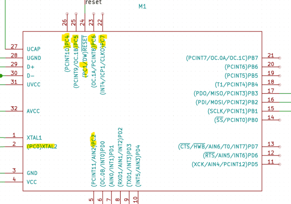
Here is the pinout of the microcontroller:

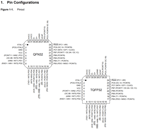
Let's talk about this pin out shall we!!

GND and V_CC (pins 3 and 4, switched between the two different configs) are the ground and
power of the microcontroller.
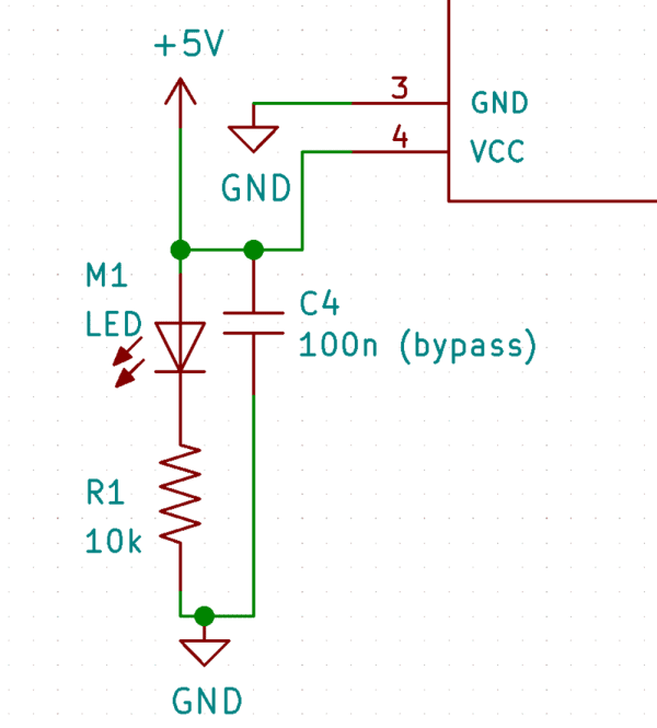
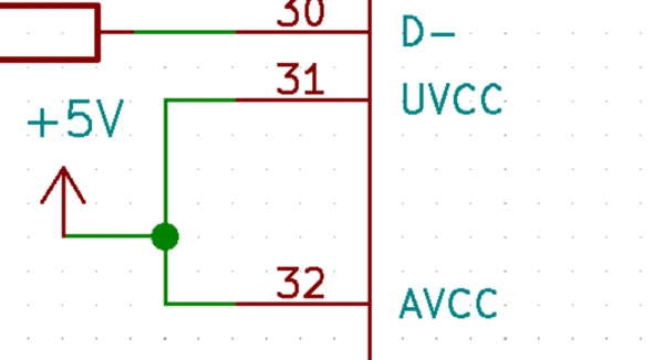
I added an LED to indicate when the chip is being powered and a bypass cap to gnd.

AVCC (pin 32) is the power source to the analog pins. I think of this like Analog + VCC.
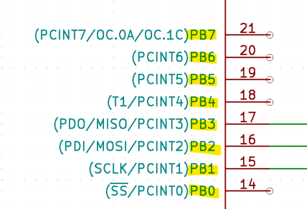
Port B pins (pins PB7-PB0, pins 14-21 for both pinout configs) "Port B is an 8-bit
bi-directional I/O port with internal pull-up resistors (selected for each bit). The Port B
output buffers have symmetrical drive characteristics with both high sink and source
capability. As inputs, Port B pins that are externally pulled low will source current if the
pull-up resistors are activated. The Port B pins are tri-stated when a reset condition
becomes active, even if the clock is not running" So these pins can act as input or output
ports, as defined by the used in embedded programming.
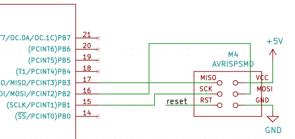
Pins 17, 16, and 15 are the MISO, MOSI, and SCLK pins for communicating with the programmer.
Here is connect them to a 6-pin header for interfacing to the programmer (either the one from
week 5 or the Atmel-ICE (AVR) in the lab). Ideally I'd like to program my board on my own
some day, so being able to program w/ an arduino would be really nice.
There are a ton of articles online on how exactly to do this.  You can also program this chip
via USB port because it comes with DFU (device fireware updater) bootloader. I'm not sure what
approach will be beter for me. I'm still inteimiadated by setting fuses, make files, etc. The
arduino route is certainly less involved/intimidating.
Port C pins (pins PC7-PC0, pin locations a little spreadout for both pinout configs) These
pins act just like port B pins. Recall pins can have alternate functions! PC0 is the XTAL2
pin, PC1 is reset.
big questions... where is PC3???

Port D pins (pins PD7-PD0, pins 6-13 for both configs)
This port serves as the analog inputs to the analog comparator. What's an analog comparator?
It's this (and we can see it on the left side of the block diagram):
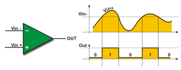
"An analog comparator can be used to compare two voltage levels and based on that it can be
used to generate a logic output (0 or 1) to indicate which of the two levels is higher or
lower than the other."  Source
The Analog Comparator compares the input values on the positive pin AIN0(PD0) and negative
pin AIN1 (PD1). When the voltage on the positive pin AIN0 is higher than the voltage on the
negative pin AIN1, the Analog Comparator output, ACO, is set (bit 5 of the Analog Comparator
Control and Status Register).
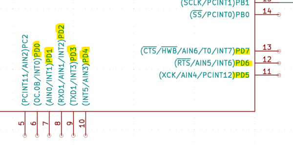
If the analog comparator is not used (PD2/PD1 pins) Port D acts just like port B or C. I'm
not using the analog comparator!

There are 22 programmable Input/Output (aka I/O) pins.
The 22-programmable pins are coming out of the PORTD, PORTC, and PORTB drivers.

D+ and D- pins (pins 29 and 30) These are the USB Full Speed Negative Data Upstream Port and
Positive Data Upstream Ports, respectively.
Source: Embedded Programming
- How can I adapt Jaclyn Berry's blinking code for my specific board?
You must change the pin definitions in the code to match your board's physical pins and adjust the board and programmer settings within the Arduino environment. - What steps did the author take when the Arduino could not identify the USBtiny programmer?
The author replaced a faulty connecting cable made for the board and programmer, then downloaded the missing USBtiny driver to resolve the issue. - Why did the make function initially fail during the C-program setup?
The failure occurred because Windows automatically added a .txt extension to the files; renaming them in Atom fixed the problem. - What software tools were required to compile C-programs for the Attiny44?
The process required installing the Atmel GNU Toolchain, GNU Make, AVRDUDE, and updating the system PATH variable. - Does the ATMEGA16U2-AU use Harvard architecture?
Yes, this 8-bit AVR microcontroller runs on the Harvard architecture system where separate memory systems store instructions and data. - What are the primary functions of Port B pins on the ATMEGA16U?
Port B acts as an 8-bit bi-directional I/O port with internal pull-up resistors that can serve as inputs or outputs depending on the configuration. - Which pins on the ATMEGA16U are used for SPI communication with the programmer?
Pins 17, 16, and 15 correspond to MISO, MOSI, and SCLK respectively for communicating with the programmer. - Can the ATMEGA16U be programmed via a USB port?
Yes, the chip comes with a DFU bootloader which allows it to be programmed via the USB port.