Contents
hide
Summary of ESP8266 / NRF24L01 Breadboard Adapter
This article describes a DIY method to create a breadboard adapter for nRF24 or ESP8266 breakout boards without soldering the modules themselves. The process involves cutting and assembling a veroboard with headers and pins to ensure proper alignment for easy prototyping.
Parts used in the Breadboard Adapter:
- Veroboard
- Headers (strips)
- Pins
- Soldering iron
Have you ever been anxious to receive your new break-out boards, only to find out that the pin layout is not breadboard friendly? If only those pins were aligned differently.

Well, let me show you how I have made an easy breadboard adapter that will fit the nRF24 or ESP8266 boards. No modifications or soldering is required on the modules itself.
Step 1: Preparing the Components
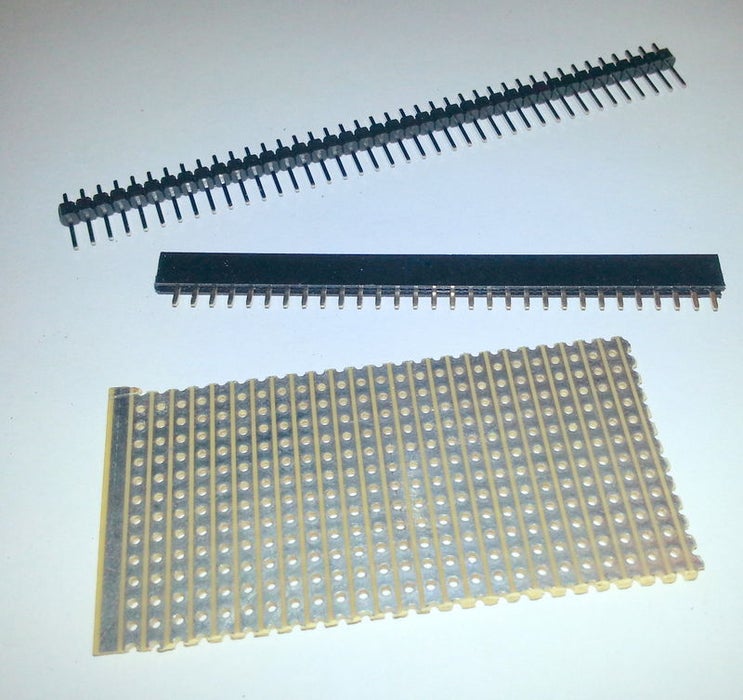
You will need a piece of veroboard, and some headers and pins.
- Cut a piece of veroboard into a 4 x 4 hole square (or the size you require).
- Use a very sharp cable or hobby knife to cut the strips in between the center of the holes as shown in the picture.
- Cut two headers from the strip, each with 4 sockets.
- Cut two rows of pins, each with 4 pins.
- Using long nose pliers, press the pins flush with the plastic holding them together.
Step 2: Assembly of the Header Connectors
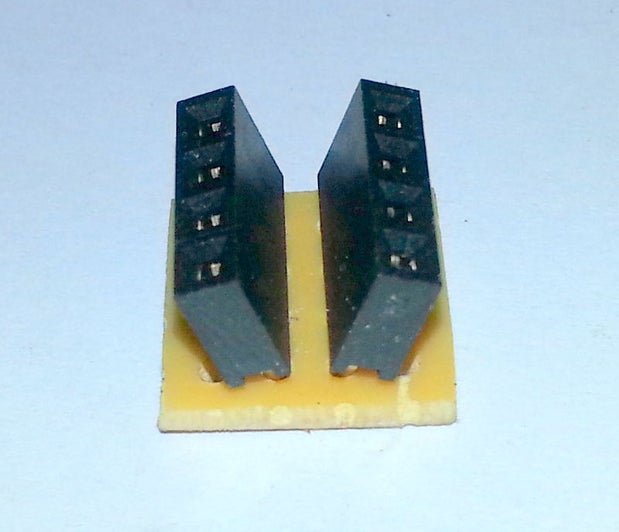
- Place the 2 headers on the board.
- Insert extra pins into the headers. This will keep them aligned during soldering.
- Solder the headers to the board.
- Remove extra pins used for alignment.
- After soldering, ensure that there are no shorts between the pins.
Step 3: Assembly of the Pins
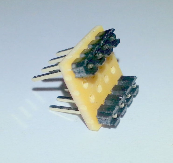
- Insert the pins from the top of the board so that the plastic is flush with the board.
- Use spare headers to keep the pins aligned during soldering.
- Solder the pins to the board.
- Remove spare headers used for alignment.
- Again, ensure that there are no shorts between the pins.
If all went well, your adapter should look similar to the photos.
Step 4: Using the Adapter
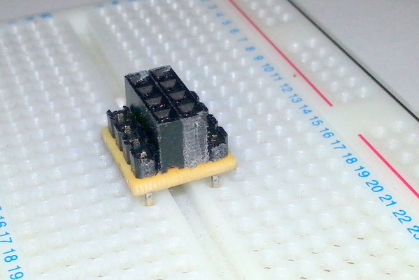
The adapter will now fit snugly into the breadboard, leaving enough room for your connections or wires. After all the connections are done, simply insert the ESP8266 or nRF24 module into the adapter.
Source: ESP8266 / NRF24L01 Breadboard Adapter
- What is the purpose of this project?
To create an easy breadboard adapter that fits nRF24 or ESP8266 boards. - Does this require modifications to the modules?
No, no modifications or soldering are required on the modules themselves. - How do I prepare the veroboard?
Cut a piece into a 4 x 4 hole square using a sharp cable or hobby knife. - What tools are needed to cut the strips?
A very sharp cable or hobby knife is used to cut the strips between the center of the holes. - How many headers and pins are required?
You need two headers with 4 sockets each and two rows of pins with 4 pins each. - How can I keep components aligned during soldering?
Insert extra pins into headers or use spare headers to keep pins aligned while soldering. - What should be checked after soldering?
Ensure there are no shorts between the pins. - How does the adapter fit into the breadboard?
The adapter fits snugly into the breadboard leaving room for connections or wires.