Introduction
Our final project in ECE 476 is a mobile robot with a developed neural network such that it evolves to avoid collisions into a circular vertical white wall while traveling at the fastest speed and straightest line possible without human intervention or external computers.

The completion of this project required extensive capacity and application on both hardware and software ends. In constructing the robot, we needed to build the custom prototype board, apply infrared sensors as neural inputs, implement stepper motors for robot motion, and provide a mobile power supply to the MCU. The purpose of these design factors is to allow the autonomous movement of the robot while minimizing the size of our robot, to accurately sense distance and collisions into the white wall of our arena, and to calculate the velocity precisely while providing sustainable torque to move our robot. On the software end, we needed to execute an evolutionary spiking neurons algorithm that interfaced with our hardware. The purpose of this was to integrate a spiking neural model with infrared sensors as inputs and motor speeds as outputs to determine robot velocity and direction. We also implemented the evolutionary model based on assessing random individuals of a randomly generated population through a fitness equation and improving the population by discarding the worst individual in the population with the worst fitness. The fitness equation measured by the velocity of the robot, the direction change, and the amount of activity from sensors.
High Level Design
Rationale and Sources
While our partnership coalesced from our strong interest in projectile devices and their implementation through use of microcontrollers, which is why we signed up the class initially, we were unfortunately denied of such opportunity as a final project.
Nonetheless, we wanted our final project to be a valuable challenge that tested our comprehensive knowledge of electrical and computer engineering. We wanted a final product that was significant to society, unique to the course, beyond the scope of previous labs, unprecedented by previous final projects, and realistic to our abilities.
Therefore, after consulting with TA Idan Beck as well as previous and current students of this course, we decided to build this robot with a genetic evolutionary algorithm.After speaking with Professor Land and previous students of the course regarding the feasibility of our project and workload involved, we formed the following objective:
- To produce a mobile robot with the neural network that autonomously avoids collisions into the white wall of a circular arena.
Background Math
We had no complicated derivations or integrations were involved in the calculations of this project. The math background needed for this project was geometry for stepper motor calculations, conversions to calculate velocity, timers, analog to digital, measurement units, algebra for analysis of the fitness equation and characterization of polynomials for infrared sensor behavior, and probability to analyze infrared sensor data, their polynomial characteristic equations, and corresponding least squares approximation and residuals.
Logical Structure
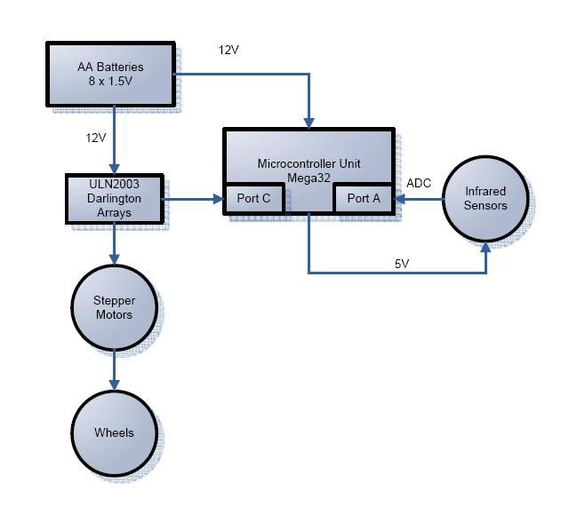
We used 8 AA batteries at 1.5V each as our mobile power supply. The 12V powers the Mega32, the Darlington arrays, and the stepper motors. The stepper motors are controlled by the Mega32 through Port C. The infrared sensors are powered at 5V and go through the ADC through Port A.
Hardware/Software Tradeoffs
After consulting with Bruce on possible approaches of neural theory, hardware, and software considerations for our neural network robot, we came across one significant hardware-to-software tradeoffs. Bruce introduced to us Hopfield and Hebbian neuron spiking networks, both of which require nonlinear amplifiers to simulate the analog inputs and spiking. He also referred us to Dario Floreano’s paper, “Evolutionary Bits’n’Spikes” (see References), that described a spiking neuron model algorithm based on incoming spike contributions to the connectivity of the network and an evolutionary model improving its population based on a simple fitness equation of speed, amount of collisions, and amount of infrared sensor activity.
Between implementing the spiking neural network on hardware or software, we chose software. We felt that hardware would take more tedious manual labor, be harder to debug, and create extra weight on our robot. With software, we can compile and debugged efficiently on CodeVisionAVR and have flexibility in adding and modifying our code.
Standards and Patents
We had no patents to adhere to in this project.
In terms of patents, lab TA Idan Beck gave us “Artificial Life IV”, a book with compilations of published papers on artificial intelligence and genetic algorithms. We got our idea of building an autonomous evolutionary robot from there, particularly the copyrighted Khepera robot. However, Floreano’s experiment and paper provided such substantial background on neural and evolutionary models for our project plan that we significantly based our final project off of his work. In adhereing to intellectual property, we exchanged emails for Floreano regarding permission to use the content described in his paper and contacted him for help when we came across a road block regarding initialization of our robot (see Intellectual Property Considerations).
Hardware
Components required for our hardware design:
- Structural design
- Wood base, wooden wheels, free rotating wheels, foam core
- Custom prototype board and Atmel Mega32 microcontroller unit
- Stepper motors and Darlington arrays
- Infrared light-emitting diode and phototransistor
- Power supply
Structural Design
The design of the robot was circular for the purpose of better interaction with our software in developing the neural network. The symmetry of this design allows the robot to detect infrared sensor inputs with more accuracy when approaching the wall and more balance between the left and right sides, in comparison to square or rectangular. The circular shape gives better turning radius in our arena, especially when the robot is in close proximity to the wall and needs to make a quick turn.
A mechanical challenge for the design was finding all the suitable parts to assemble the rectangular base of our robot. We used two wooden wheels that attached perfectly to the stepper motors. Two more free rotating wheels were used to keep balance and permit mobility of the robot. We used L-brackets, nuts, bolts, and spacers to install the stepper motors onto the wood base
To minimize the robot’s size, we created two layers: one for the power supply and one for the circuit boards. Thus, the foam core circles were no larger in diameter than the protoboard and solder board side by side.
Prototype board and Atmel Mega 32
The protoboard was assembled by following the instructions on the protoboard design page. Because the robot was running off batteris and not the AC power supply, we connected our 12V battery supply directly to the power ports on the protoboard. To program the Mega32, the 6-pin programming port was used throughout this project. Pins D.0 and D.1 of our Mega32 were used to display values through hyperterm.
The Port C pins were used to connect the Mega32 to the input of the Darlington arrays for the stepper motors. Port A was used to converting the analog voltage from the infrared sensors to the digital signals as inputs for our program. The remaining available pints on the protoboard were used to lay out the infrared sensor circuits.
Stepper Motors
The robot used PF35T-48L4 stepper motors to move forward, backward, or turn. The reason we chose stepper motors is because they offer precise control over the speed and direction of the robot. Because velocity of each wheel is an output of the neural network and is used to compute the fitness equation of each individual in our evolutionary model, the stepper motors’ accuracy was a key factor in our hardware design.
Stepper motors move at 7.5 degrees/step with one step at a time because each step in the motor draws 500mA at a time. To calculate the velocity of our robot, we know that 360/7.5 gives us 48 steps/rev. The diameter of our wheel is 2 inches, so (2 inch * 2.54 cm/ in * pi / 2) = 15.9593 cm/rev. Velocity is then 15.9593 cm / rev * 1/48 rev / (t2 / 1000 s) = .332485 cm / (t2/1000 s). Therefore, we could control the velocity of our robot by determining the value of t2.
The red and green wires of our stepper motor are connected to our 12V battery supply. We connected left motor pins C.0-C.3 to orange, yellow, brown, black, respectively. Likewise, we connected right motor pins C.4-C.7 in the same color order.
We needed to use Darlington arrays to connect the Port C pins as inputs from the Mega32 into the ULN2003AN and the outputs to the stepper motors. Darlington arrays output high voltage with common-cathode clamp diodes for switching inductive loads. Each pair operates at 500mA, which matches the current of each step in a stepper motor.
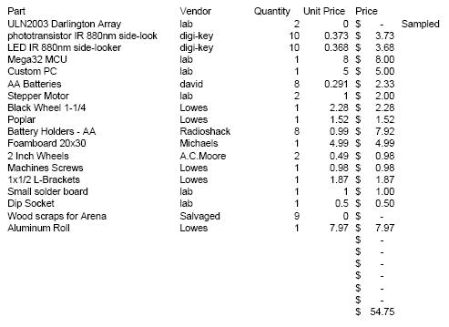
Parts List:
For more detail: Evolving neural robot Using Atmega32