Summary of MCU MIDI synthesizer using Atmega32
This project implements a subtractor synthesizer using an Atmega32 microcontroller to generate diverse musical sounds via waveform manipulation. The system features 8-channel polyphony, two oscillators with multiple wave types, ADSR envelope control, and a MIDI interface for keyboard input and velocity detection. It includes an LCD menu, potentiometers for parameter adjustment, and a tone shifter for pitch modification, capable of playing three demo songs.
Parts used in the Atmega32 Music Synthesizer:
- Mega32 microcontroller
- Custom PC board
- 6N138 optoisolator
- 10KOhm Potentiometers
- LCD display
- 3904 npn BJT
- Project box
- Audio out jack
- MIDI Din-5 connector
- Assorted resistors
- Assorted capacitors
- MIDI keyboard
- Speaker
- Push buttons
Introduction
Our final project is a music synthesizer that is capable of producing a variety of musical sounds, by modify, the attack, decay, sustain, release times, and applying special effects such as a low pass filter or a halftone shifter.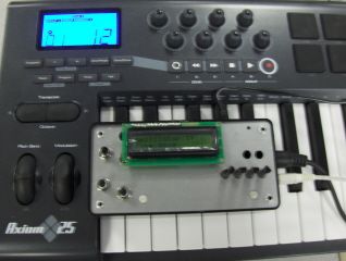
Our original interest for this project came from one of our TA’s (Idan Beck) while we were talking about the second lab (Cricket Call Generator). He told us about how just by changing the waveform, we can change the sound created by the generator from a cricket call to something more interesting such a musical instrument. That lead us to a conversation about how a synthesizer work, and how close they are to the cricket call generator. Since both of us play an instrument (Min piano, and Franco guitar) we thought it would be interesting to do a project that aimed at simulating these instruments. It seemed like it would be interesting to learn about why instruments sound the way they do, and how to manipulate waveforms to achieve the desired sound.
Summary
Our final design for the synthesizer was a Subtractor Synthesizer with the following properties:
-8 channel polyphony to allow for multiple note presses
-2 Oscillators each capable of producing a Sine, Square, Triangle, and Sawtooth Wave
-Ability to add, subtract, multiply and low pass filter the two oscillators
-4 knobs to control the Attack, Decay, Sustain and Release(ADSR) time
-Interfaces with a midi keyboard control, with the ability to detects pressure of button press on key (i.e. loud for hard strike, quiet for soft strike)
-LCD menu and 3 buttons to scroll through and turn on and off functions.
-Tone shifter capable of shifting in Halftones from an octave below to and octave above the note pressed.
-Capable of playing 3 musical demos (“Canon in D”, “Fur Elise”, “Row Row Row You Boat’ Rounds)
Theory
Background Math
The main background math we needed to successfully finish this project was 8:8 fixed point notation and mathematic representation of waveform. For the fixed point math we mostly referred to the ECE 476 web page[1]. The main idea is that we used Int to represent floating point values by putting the binary point between bit 7 and 8. This gives us a range of +/- 127 with a resolution of .00396. By using floating point math we were able to dramatically decrease the amount of computation in comparison to floating point math. This allowed us to fit all the code we needed into the sound generation interrupt.
Waveform Creation
In order to create the different waveform we used a basic x-y map layout of the wave via a 256 size char array, where each array represents a “x value” and the “y-value” is stored in the char. Once we have one period of the wave we could then just keep repeating it to make our sound wave.
ADSR
The Attack, Decay, Sustain, and Release times are the most common parameters in a generic synthesizer. Attack is how fast the amplitude of the waveform raise when a note is played. Decay is how fast the amplitude drops to sustain after the attack. Sustain is the amplitude of the note when held down. Release determines how long the not persists after the user has stopped pressing the note. Together these four waves determine the sound of the note. Changing the ADSR will alter the waveform entirely. For example, raising the Attack time will create a more hollow/windpipe sound, while changing the decay will create more of a string sound. Release will bring more of a resonance sound and the sustain level will determine if the sound is more like a pluck or a press. This enveloped modulation can be seen the following picture.
MIDI
Midi is a communications protocol designed for digital instruments. Midi devices do not transmit audio signals but instead digital event messages that tell the receiving end what the device is trying to do. Midi messages are sent via a serial connection at 31,250 bits per second. Each midi byte consist of 1 start bit( zero), 8 data bits, and one stop bit (one), there are no parity bits. There are many messages that a midi device may send, which vary in length and content. With all messages the first byte is always the status byte, which tells the receiving end what to do with the data that follows. The high nibble of the status byte is the information about what event to perform and the low nibble says which channel to perform that event on. After scoping the output of our keyboard we found that it sends all status bytes with a low nibble of 2, meaning perform event “status byte high nibble” on channel 2. Some common status bytes include NOTEON (0x92), NOTEOFF(0x82), PITCHWHEEL(0xE2). The most common messages consist of 3 bytes, a status byte followed by a note byte followed by a velocity byte. The velocity byte is an encoding of how hard the key was hit to find out how loud to play a note, the range is from 0 to 127. This 3-byte message would be sent when pressing a key on a midi keyboard. For example, if you pressed middle C semi-hard on the a midi keyboard it might send a 3-byte message of 0x92, 0x3C, 0x64, which would correspond to a message that says play middle C at a relative loudness of 100. When a note is released a 3-byte message with NOTEOFF at the status byte is sent. Some keyboards, i.e. the one we used, send a NOTEON status byte when a key is released but with a velocity of 0, this is interpreted as a NOTEOFF message, telling the receiving end to stop playing a note. For our purposes the only messages we concerned ourselves with were messages with a status byte of NOTEON.
Music Notes
The basic princples we needed to know about the frequencies is that starting with the note A(440 Hz), we can can increase or decrease the halftone by multiplying or dividing the value by the twelfthroot(2). From there we have the frequency for all the notes in the scale.
Polyphony
Polyphony is the ability to run mutliple channels of music waves at the same time. This allows us to hit chords and run several musical tunes simultaneous. A high number of polyphony is desirable.
Hardware
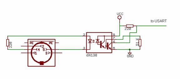
Midi Interface
The midi device and the microcontroller needed to be electronically isolated to prevent damage to both devices and to keep the current loop that transmits the midi messages from sinking into the mcu. We use an opto-isolator to perform this task. We first designed the opto-isolator circuit using the 4N35 opto-isolators available in lab. At a 31,250 baud rate a bit is sent every 32 microseconds, the rise/fall time of any following circuit needs to be about 5 microseconds. Even with a 51KOhm resistor attached between the base of the 4N35s BJT and ground to lower the fall/rise time the fall/rise time was not fast enough to reproduce the signal properly on the other end of the opto-isolator. We changed the 4N35 to a high-speed 6N138 and with a 51KOhm resistor between the output BJTs base and GND we obtained a much faster fall/rise time. The signal looked more like a square wave but still had a logarithmic growth that was not ideal. The 6N138 inverts in the input signal which is a problem. RS232 protocol requires a serial signal to idle high, a low start bit, and a high stop bit. To invert the output of the 6N138 we used a simple transistor (npn BJT) inverter with a 10KOhm resistor at the input (base) and a 1KOhm from output to VCC. This inverter fixed the non-ideal logarithmic growth at the output of the 6N138 since all outputs of the inverter can only be VCC or GND. After being isolated and then inverted the midi signal is now ready to be sent to UART to be sampled 31,250 times per second.
LCD/potentiometers/Pushbuttons
Potentiometers and pushbuttons were used to select the many options of our synthesizer, while the LCD displays the menu of the current settings you can change. We ordered 10KOhm trimpots with knobs to adjust the attack, decay, sustain, release time. The output of the potentiometers will be between 0-5V, this range gets read into an ADC to convert into a value that corresponds to a time on the interval 0 -1000ms. Active low push buttons are used to select which menu you display on the screen.
Parts List:
| Item | Quantity | Cost | |
| Mega32 | 1 | $0.00 | donated by Marcelo Garza(last semester project) |
| custom PC board | 1 | $5 | |
| 6N138 optoisolator | 1 | $1 | digikey |
| 10KOhm Potentiometers | 4 | $1.00 | allelectronics |
| LCD | 1 | $8.00 | lab |
| 3904 npn BJT | 1 | $0.00 | lab |
| project box | 1 | $0.00 | previous year box |
| audio out jack | 1 | $0.00 | previous year box |
| midi Din-5 connector | 1 | $0.00 | previous year box |
| assorted resistors | 10+ | $0.00 | lab |
| assorted capacitors | 2+ | $0.00 | lab |
| midi keyboard | 1 | $0 | Donated by TA(Idan) |
| speaker | 1 | $0 | Previously Owned |
| push buttons | 3 | $0 | Previously year box |
| Total | $15 |
For more detail: MCU MIDI synthesizer using Atmega32
- How does the system handle floating point math?
The system uses 8:8 fixed point notation by placing the binary point between bit 7 and 8 to decrease computation time. - What components are used to isolate the MIDI signal?
An opto-isolator (specifically the 6N138) is used to electronically isolate the MIDI device from the microcontroller. - Can the synthesizer play chords?
Yes, the 8 channel polyphony allows for multiple note presses simultaneously to play chords. - How is the loudness of a note determined?
The velocity byte from the MIDI keyboard encodes how hard the key was hit to determine relative loudness. - What waveform types can the oscillators produce?
Each oscillator can produce Sine, Square, Triangle, and Sawtooth waves. - How are the Attack, Decay, Sustain, and Release times controlled?
Four knobs connected to 10KOhm potentiometers allow users to adjust these specific time parameters. - What is the baud rate for the MIDI communication?
Midi messages are sent via a serial connection at 31,250 bits per second. - Which musical demos can the synthesizer play?
The system is capable of playing Canon in D, Fur Elise, and Row Row Row Your Boat Rounds.