
Summary of DIGITAL TONE CONTROL CIRCUIT ATMEL ATTINY2313 LM1036
This article describes a digital tone control circuit using an ATtiny2313 microcontroller and LM1036 chip. The system adjusts bass, treble, and balance via PWM channels controlled by menu keys (+/–) and displays values on an LCD. Settings are stored in EEPROM, and the design includes provisions for future expansion using pin change interrupts. The project was tested with a STK4241 amplifier, showing functional results despite some image distortion during testing.
Parts used in the Digital Tone Control Circuit:
- ATtiny2313 microcontroller
- LM1036 chip
- LCD screen
- Mute button
- Menu keys (+ and –)
- EEPROM
- STK4241 amplifier
- 74244 parallel port programmer
- ISP connector
Recently a similar application I’ve done, but ds1844 integrated can not be found had been a problem AVR reviewing ATtiny2313 `fame four PWM channels, saw direct this practice came to my mind bass treble…Electronics Projects, Digital Tone Control Circuit Atmel ATTINY2313 LM1036 “avr project, microcontroller projects, “
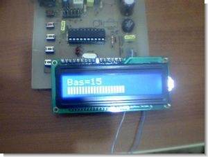
Recently a similar application I’ve done, but ds1844 integrated can not be found had been a problem AVR reviewing ATtiny2313 `fame four PWM channels, saw direct this practice came to my mind bass treble balance sound ATtiny2313 4pwm channel using lm1036y by checking this practice have realized circuit isis simulated in whether board on the tried digital part Your question worked last lm1036 pcb `t hooked up and amp draw on the results stk4241 hooked to the output circuit works just fine.
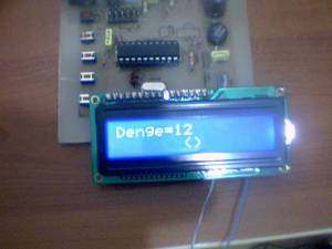
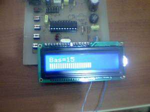
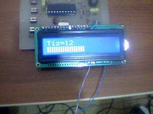
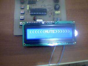
Circuit general characteristics of the menu key and select the make + – keys values are adjusted PWM resolution 8bit because between 0-255 setting is making the LCD screen, the ones digit by not showing 0-25 inter-level showed also the circuit on the mute button’s bass treble balance sound values eeprom Save it to the values for the 2nd row is showing in the form of hard kalıyor.değer bar.
There is also a pcb on the tk19 place for left future control add the control in your hands to time use only pin change interrupt employees with stock code if you are located circuit can add, because timers PWM generation is used in further circuit isp connector adding ATtiny2313 circuit on the I program the programmer as 74,244 `s very simple parallel I’m using port programmer circuit test video I took but a very distorted image
DIGITAL TONE CONTROL CIRCUIT TEST
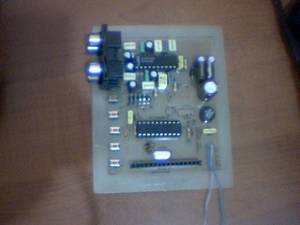
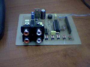
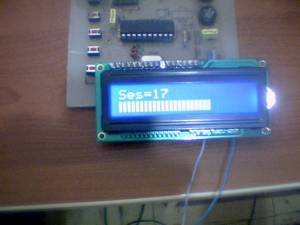
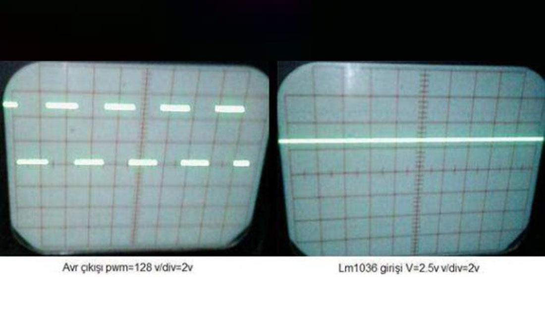
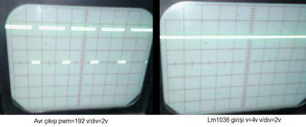
ATTINY2313 LM1036 INPUT OSCILLOSCOPE MEASUREMENTS
Digital Tone Control Circuit source cone and schematic pcb files: digital-tone-control-circuit-atmel-attiny2313-lm1036.rar
- What components are used in the digital tone control circuit?
The circuit uses an ATtiny2313 microcontroller and an LM1036 chip. - How is the PWM resolution set in this project?
The PWM resolution is set to 8-bit because the value setting ranges between 0-255. - Does the circuit save settings permanently?
Yes, the bass, treble, and balance sound values are saved to EEPROM. - Can the circuit be expanded for future controls?
Yes, there is a place on the PCB for adding future control features using pin change interrupts. - How does the user adjust the audio values?
Users adjust values using menu keys labeled + and – which update the LCD screen. - What amplifier was connected to the output circuit?
A STK4241 amplifier was hooked to the output circuit and worked fine. - Is the programming of the microcontroller simple?
Yes, the programmer circuit using a 74244 parallel port is described as very simple.
