Summary of DIY milliohmmeter
This article describes a DIY milliohmmeter using an LT3092 current source and INA225 current sense. It measures resistance by applying constant current and reading voltage output. The circuit supports standalone operation with an MCU or connection to a DMM, offering high accuracy and stability via an LT1461 voltage reference.
Parts used in the DIY milliohmmeter:
- LT3092 (Current Source)
- INA225 (Current Sense)
- MCU with 10-bit ADC
- LCD Display
- Digital Multimeter (DMM)
- LT1461 (Voltage Reference)
- Connecting Cables
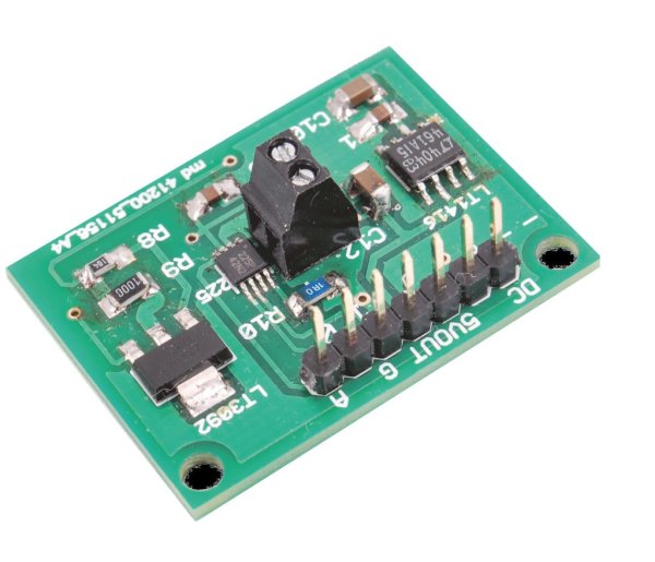
This is an example of a simple and cheap milliohmmeter that can be made by every maker. The core of the circuit are a current source (LT3092) and a current sense (INA225): a costant current flows through the milliohm resistor under test and the voltage at the current sense output gives the value of the resistor (V=R*I).
The milliohmmeter can be used as a stand alone instrument by adding a MCU with at least 10 bit ADC and a LCD display or it can be used togheter with a DMM.
Current out from LT3092 can be set between 0.5 mA and 200 mA with 1% accuracy; INA225 gain can be set to 25, 50, 100 or 200 (0.3% accuracy). By setting Iout from current source equal to 10mA (Iout=10*R2/R3 uA) and current sense gain equal to 100, 1Ω = 1V and 1mΩ = 1mV as such the milliohm resistor value can be easily measured in mV using a DMM, without any kind of conversion. A voltage reference (LT1461) has been added to the circuit in order to have a precise and stable voltage, useful to power both the current source and the current sense as well as the the MCU and its ADC in case we want to have a stand alone milliohmmeter.
#include “mbed.h”Serial pc(USBTX, USBRX); // tx, rxfloat VADC=2.922; //ADC VOLTAGE REFERENCE (EQUAL TO V SUPPLY)//float IO=10.0; //COSTANT CURRENT//float GAIN=100.0; //INA225 GAIN//BOTH NOT REQUIRED IF SET LIKE THIS (1 Ω = 1 V)float RO=0.021; //RESISTANCE OF CONNECTING CABLES (COMPENSATION)float STAMPA_R = 0;AnalogIn resistor(A0); //CONNECTED TO INA225 OUTfloat ohm(){float R=0.0;float RADC=resistor.read();R = VADC*RADC-RO; //IF IO=10mA AND INA225 GAIN 100 -> (1 Ω = 1 V)wait_ms(100);return R;}int main(){while (1) {STAMPA_R= (ohm());pc.printf(“R = “);pc.printf(“%1.3f”,STAMPA_R); //R IN OHM WITH 3 DECIMALS (1mΩ OF RESOLUTION)pc.printf(“Ω”);pc.printf(“\r”);wait_ms(500);}}- What is the core of the milliohmmeter circuit?
The core consists of a current source (LT3092) and a current sense (INA225). - Can this device be used as a stand-alone instrument?
Yes, it can be used standalone by adding an MCU with at least a 10-bit ADC and an LCD display. - How can the current out from the LT3092 be set?
It can be set between 0.5 mA and 200 mA with 1% accuracy. - What gain options are available for the INA225?
The gain can be set to 25, 50, 100, or 200 with 0.3% accuracy. - Why was a voltage reference added to the circuit?
An LT1461 was added to provide a precise and stable voltage for powering the components. - Does the code compensate for cable resistance?
Yes, the variable RO represents the resistance of connecting cables used for compensation. - What resolution does the provided code offer for resistance measurement?
The code outputs resistance in Ohms with 3 decimals, providing 1mΩ resolution.