Summary of Fun Micro:bit Robot – EASY and Inexpensive!
This article details an inexpensive, beginner-friendly robot car project using a BBC micro:bit and recycled materials like tissue boxes. It guides students through assembling the chassis, wiring components on a breadboard, and programming the micro:bit to control motors via Bluetooth and accelerometers. The project emphasizes low cost, no power tools, and minimal soldering, making it ideal for elementary classrooms.
Parts used in the Micro:bit Robot Car:
- Tissue box
- Box cardboard (corrugated)
- Solid core wire
- BBC micro:bit (2 units)
- micro:bit GPIO Edge Connector
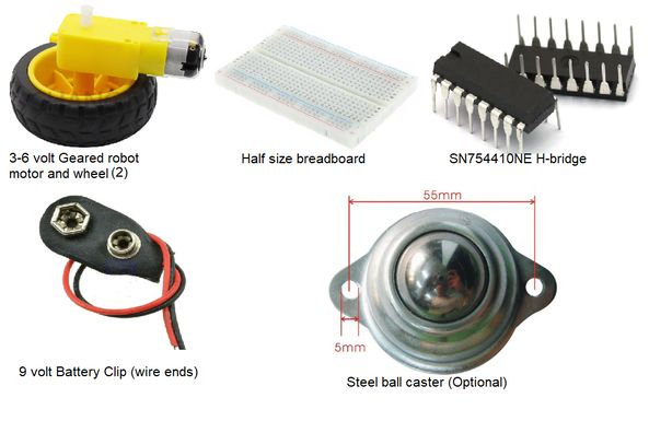
- Geared Motor/wheel (2 units)
- Mini breadboard
- 9Volt Battery clip
- SN754410NE Motor Chip
- Ping Pong Ball
- Ball caster (optional)
- Two-sided foam tape
- White glue
BBC micro:bits are great! They are easy to program, they’re packed with features like Bluetooth and an accelerometer and they’re inexpensive.
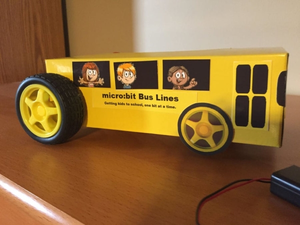
Wouldn’t it be great to be able to build a robot car that costs next to NOTHING? This project is inspired by the desire for elementary school students to be able to build robots using a minimum of parts and wherever possible, use recycled materials. It takes very little time and encourages students to learn coding, some engineering and to use their craft skills. There’s no cutting or drilling with power tools and no soldering. The primary building materials are a FACIAL TISSUE box (ex. ‘Kleenex’) and a bit of box cardboard. It can be completed in a few days of class time.
You’ll learn some electronics, basic micro:bit coding and how to use the accelerometer and Bluetooth features of micro:bit.
So let’s get started!
Step 1: Parts List
Parts List
Item Cost Quantity
Tissue box free 1
Box cardboard (corrugated) free 2 pieces that fit in the bottom of the box for stiffening.
Solid core wire minimal Enough for the wiring for the project
BBC micro:bit retail 2 – one for transmitter, one for the car controller
micro:bit GPIO Edge Connector $6 to 15 US 1
Geared Motor /wheel $3 US each 2
Mini breadboard $0.75 US 1
9Volt Battery clip $0.25 US 1
SN754410NE Motor Chip $0.40 US 1
Ping Pong Ball minimal 1
Ball caster (optional) $1.20 US 1 – can use half a ping pong ball or marble instead
Two-sided foam tape $2 at dollar store 1roll – for mounting the motors to the base
White glue You’ve probably already got some
Tools Needed
A ruler
A small utility knife
Hot Glue Gun (optional)
Paper clip or compass for piercing small holes in the tissue box
Rotary cutting tool(optional) or razor saw to cut the ping pong ball in half.
Step 2: Robot Construction
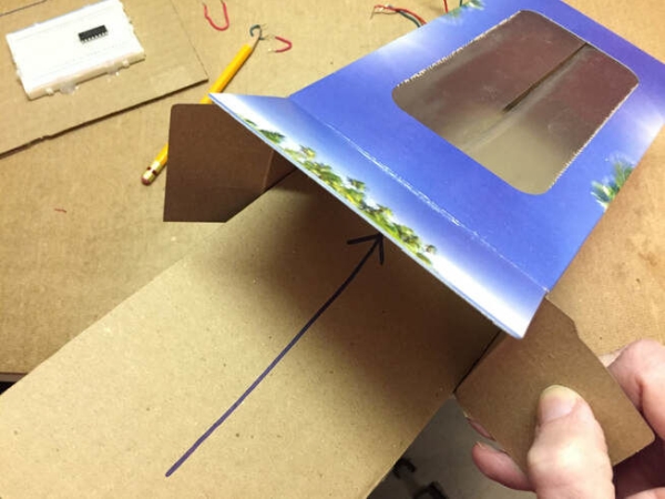
Place the tissue box on the corrugated cardboard sheet so the long side of the box is in line with the ridges of the cardboard. Trace the base of the tissue box on the cardboard. You’ll need two pieces. Carefully cut out the pieces with the knife and ruler. You should trim them so they will fit flat inside the box.Carefully open one end of the tissue box to test fit the cardboard sheets.
Use white glue or carpenter’s glue to glue one piece of the cardboard to the inside base of the box. Put some heavy objects like batteries inside the box to weigh down the cardboard so it will fasten securely to the box. Let it dry.
Before we go further, you may wish to solder short lengths of solid-core wire onto your motor wires and 9 volt battery clip wires. Then cover the joints with heat shrink tubing. It will make it easy to insert these wires into the breadboard. I know I said, “No soldering”, but hey, this IS electronics!
Step 3:
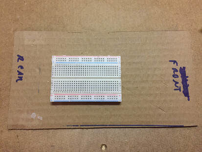
Now start laying out the parts on the other piece of cardboard as shown. Try to mount the breadboard towards the end that will be the rear of the car so the micro:bit and edge connector fit. For consistency, the red-rail of the board is at the top of the pictures. It’s recommended you orient yours the same way for ease of assembly.
Hot glue is great for attaching the breadboard. Then you can easily remove it if you want to use it for another project. DO NOT USE THE TWO SIDED TAPE on the bottom of the breadboard. It holds the metal connections inside the breadboard. If you pull it away, it’ll wreck the breadboard.
Step 4: Attach the Micro:bit Edge Connector
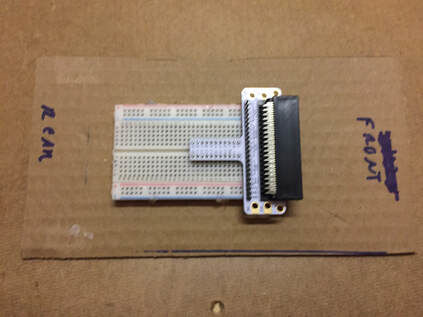
Now attach the edge connector to the breadboard as shown with the connector pointing to the front of the robot. The pins should straddle the trough(ravine) that runs along the middle of the breadboard.
Step 5: Install the SN754410NE Motor Control Chip
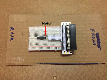
Carefully install the SN754410NE motor chip on the breadboard. The small notch should be pointed towards the edge connector.
Step 6: Wire the Motor Chip
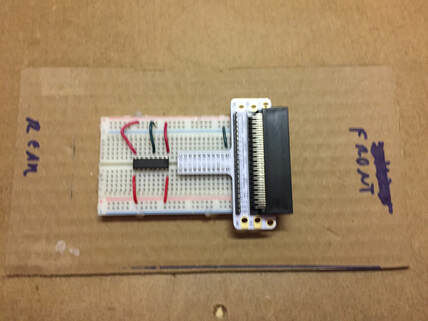
If you look down on the motor chip from above, with the notch on the right, the pins on top are numbered 1 to 8 from right to left and then the pins on the bottom are numbered from 9 to 16 on the bottom. An explanation of how the motor chip works will be provided at the end of this project.Use small lengths of wire to join,
Pin 1 to the red rail
Pin 8 to the red rail
Pin 9 to the red rail
Pin 16 to the red rail
Use a short length of wire to join the edge connector ground to the blue rail of the breadboard.Use a small length of wire to join the top-side blue rail to pin 4 OR 5 of the motor chip. It’s the chip’s GROUND point and you only need to ground the chip with one wire.
Source: Fun Micro:bit Robot – EASY and Inexpensive!
- What are the primary building materials for this robot?
The primary building materials are a facial tissue box and some box cardboard. - How many micro:bits are required for the project?
Two micro:bits are required; one acts as the transmitter and the other serves as the car controller. - Can I use power tools or soldering for the main construction?
No, the project requires no cutting or drilling with power tools and no soldering, though short wires can be soldered for ease of insertion. - How should the cardboard pieces be prepared for the chassis?
You must trace the base of the tissue box onto two pieces of corrugated cardboard, cut them out, and trim them to fit flat inside the box. - Which tool is recommended for piercing small holes in the tissue box?
A paper clip or compass is recommended for piercing small holes in the tissue box. - What specific motor control chip is used in this build?
The SN754410NE Motor Chip is used to control the motors. - How do you secure the breadboard to the base without damaging it?
Hot glue is recommended for attaching the breadboard; two-sided tape should not be used on the bottom because it can wreck the internal metal connections. - What features of the micro:bit will students learn to use?
Students will learn how to use the accelerometer and Bluetooth features of the micro:bit.