Introduction
Musical Instrument Digital Interface, or MIDI, is a standard that describes a protocol, digital interface and specific physical connections that allow electronic music devices and computers to communicate with each other. For our final project, we created a MIDI glove that is capable of connecting to a virtual synthesizer on our computer and controlling it. Additionally, we used a piece of software called “Hairless MIDI to Serial”, which aided in changing the serial data from the glove into a MIDI stream that we could output to the computer (which was our virtual synthesizer). The glove has the functionality to play a specific instrument while being able to change the pitch, change the instrument you are playing, change the key of the notes being played, and turn pitch bend on or off, causing vibrato. When your pointer finger is pressed one, the MIDI note is turned on and stays on as long as the finger is held down. The pitch of the note is changed by tilting your hand left or right about the X axis. To change instruments, you flick your hand to the right. To change keys, you flick your hand up or down. When your middle finger is held down, wiggling your hand about the X axis causes vibrato in the note.
High Level Design
Rationale and Source of Our Project Idea
We chose to do this project as both my partner and I had an interest in music and have had experience to MIDI controllers in the past. It seemed like a realistic project that would have some cool outcomes when we were done. We thought it would be a perfect idea to combine the extracurricular interest with the academic course to make this really cool device! Inertial Measurement Units have come down in price and have become very viable for musical instruments. We have always wanted to work with accelerometers and gyroscopes and this was a great way to apply it to music.
Background Math
Geometry of pitch and roll. The accelerometer gives values as the magnitude of force in the X, Y, and Z directions, this values themselves don’t give the orientation of the device. To calculate the pitch and roll of the device we used the formula:
We considering applying a digital filter to the accelerometer data to suppress noisy measurements, but we decided that the resolution we were looking for was coarse enough that a filter wouldn’t have a noticeable effect on the notes the microcontroller sent.
Logical Structure
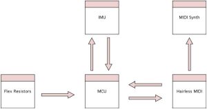
There were 3 main sections to project. The first was the 2 flex resistor connected to the microcontroller into the A0 and A1 ports, which are the analog inputs to the internal ADC. We had our accelerometer/gyroscope, the LSM9DS0, which was connected to the serial bus clock line, C0, and to the bi-directional serial bus I/O data line, C1. This is so we could take data from the accelerometer/gyroscope (we’ll use IMU as an abbreviation for the rest of the report) and manipulate it from the Mega 1284. We also had a voltage buffer circuit that helped to stabilize the voltage when there were changes in current going into the IMU. Lastly was the serial to USB converter, which allowed us to attach the microcontroller to our computer.
Hardware Software Tradeoffs
For a bulk of the processing, we relied on the Atmel Mega 1284 to handle internal calculations and any information it received from our accelerometer/gyroscope (we’ll use AG as an abbreviation for the rest of the report). The amount of hardware in this design was not very extensive. We had 2 voltage divider circuits for the flex resistor, a prebuilt AG and a voltage buffer that allowed for any current being drawn by the AG to not change the voltage. We used the AG hardware to determine values such as the heading and acceleration of the glove and sent that information via I2C/ TWI to the controller. Also, by making the design more software oriented, we were able to easily change the functionality of different specific movements of the glove by modifying the code instead of possibly having to change hardware parts to achieve a different result. We decided to not use an actual MIDI port and a 31.25 kHz signal because it has been done many times before and we decided that it would be more flexible to use a serial to USB cable to allow us to focus more on the actual sound generation.
Hardware Design
Flex Resistors
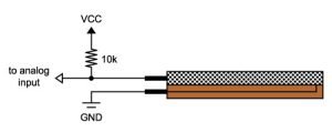
The flex resistors played a crucial role in the MIDI controller. They served as our on/off switch for different functionalities of the glove including turning a note on/off and turning the pitch bend on/off. The pointer finger was used to to turn MIDI channel 1 on and off based on the voltage output from the flex resistor circuit. The middle finger was used to control our pitch bend/vibrato. This function would only work if the point finger was also held down as you can not pitch bend a note that is not playing. We got the design for the flex resistor circuit from the Sparkfun website, where we purchased the resistors, which are essentially a potentiometer.
The flex resistors have a resistance of 30 kohms when straight and 50 kohms when bent 90 degrees, according to the website. However, the ranges weren’t that concrete when we test the resistors and we got ranges anywhere from 25 kohms when straight to about 60 kohms when bent. We took this into when writing the code that determined the threshold for “on” or “off”. The best way to incorporate the flex resistor into our design was to make a voltage divider with the flex resistor and a 10 kohm resistor. The output of the voltage divider is then fed into the analog input. With this circuit, the output will be about 75% of Vcc when straight and about 83% of Vcc when bent completely.
Serial to USB
In order to actual send MIDI signals, we first needed to be able to send serial communications between the microcontroller and the computer. For this, we used a serial to USB converter that is available to us in lab. The Tx port of the converter was connected to port D1 on the microcontroller and the Rx port of the converter was connected to port D0 of the microcontroller.
Accelerometer and Gyroscope
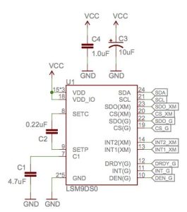
The accelerometer/gyroscope was probably the most important hardware part of our circuit. This is the piece of equipment that gave us all of our headings, directions, direction changes, and accelerations which we used to give the MIDI controller movements actual meaning. As described below, the IMU was also connected to a voltage buffer in order to help maintain a constant 3.3 V voltage source. The Vcc of the IMU was connected to this buffer circuit.
The other pins of the IMU that were used were GND, SCL, and SDA. The SCL and SDA ports were connected to the serial clock I/O pin, C0, of the microcontroller and the serial data I/O pin, C1, respectively. I2c requires a pullup resistor so that the sender can pull the line down, rather than pulling the line up which allows for mixed logic level devices.
The accelerometer part of the device is used to aid us in finding the orientation of the user’s hand. It does this by gauging the orientation of a stationary object with relation to the Earth’s surface. When you accelerating in a particular direction, it can’t distinguish that from the acceleration due to the Earth’s gravitational pull. The accelerometer can give the user a direction of gravity and with a three-axis accelerometer like we had, we were able to use it to determine the orientation of the hand relative to the Earth’s surface. This was used to determine which pitch would be played through the synthesizer. Depending on the orientation of the hand, a different note would be played. This also allowed us to determine “starting points” for functionalities that required use of the gyroscope.
The gyroscope helped us by being able to measure the rate of rotation around a specific axis. This only gives us a value while the device is still in motion. Once it stops moving, we will get a reading of zero. This was critical in some of our key functionalities. It allowed us to make a flick of the wrist to the right about the Y axis equal to an instrument change by having a threshold rotation rate of 240 degrees/second. Anything faster than that would cause an instrument change while anything slower would be ignored. We also used it to change the key of the piece of music we were playing in. Because a change in key is just a shift of all of the notes in the key by a specific half step up or down, we made it so that when the user flicks their hand up or down about the X axis, the key would either go up or down appropriately. This makes the mapping of the notes more effective. If you only have the notes in a specific key available to be played, it maps a smaller range of notes to the “pitch space”, making it easier to hit the correct notes. Additionally, if you overshoot or undershoot the note you want to play, you will just end up playing another note in that key, which doesn’t sound nearly as bad as playing something out of key. One of the last functionalities the gyro provided us was the ability to cause a pitch bend or vibrato. If both of the flex resistors were held down and you wiggle your hand about the Y axis, it will cause a vibrato in the note you are playing.
Voltage Buffer
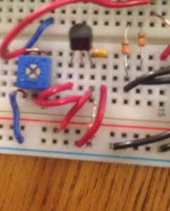
After talking with Bruce, we decided that a voltage buffer would appropriate in this circuit. The voltage buffer always gives a precise voltage controlled by the trimming potentiometer while allowing current to flow from the voltage source to ground. We needed this specifically because the accelerometer needed a 3.3 V source rather than just a 3.3 V signal. We found that the accelerometer was not functioning with just a trimpot even though the gyroscope and magnetometer were.
Final Product
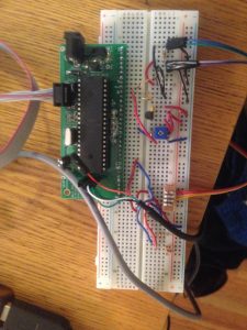
Below is a picture of the whole project together:
Software Design
Midi Stream
The generation of the midi stream was relatively straightforward. We wrote bytes to the UART serial stream which was interpreted on the computer by the Hairless MIDI software with the uart_putchar function. To send a note we sent a status byte with the note on command and the MIDI channel we wanted to play on. We then sent a 0 with a 7 byte unsigned velocity value appended, then a 0 with a unsigned 7 bit note value. We also implemented sending a pitch bend command, which had the status and channel byte, along with two data bytes containing a signed 14 value split across two bytes. We also implemented changing the instrument which had a status byte and a 7 bit data byte.
MIDI Note and Command Generation
With the MIDI standard there are note on and note off commands. This represents a key being pushed down and released. Since our instrument worked like that either your finger was bent or it was not (pressed or released). To turn off the note you need to send the same note code that was sent for the note on. When the flex resistor registered a bent finger the ADC interrupt would set a flag telling the main task to play a note. When the play_on flag was set, the main task would get the roll and pitch from the function. With this value it would call the function which calculated the note that was to be played. It would then store this note in a global variable so it could be later turned off. When the ADC interrupt found that the middle finger was bent we set a flag adc_chan1_on. If a note was playing (we had seen the play_on flag but not the play_off flag) we would use the roll of the accelerometer to bend the pitch of the note. We would get the difference in roll between when the note was played and the current roll, and bend pitch proportional to the difference. Similarly to how a note on command is sent we also send a note off command when the finger is detected to be unbent. Rather than calculated what note to turn off from the accelerometer’s roll we use the note stored in the global we set when the note was played. Each time the main task executes we also check the gyroscope to see if a “flick” gesture is happening. We see if the rate from either the X or Y axis is above a certain threshold. The threshold we chose was not an obvious decision to make. We had to make sure that it wouldn’t be inconvenient to flick your wrist at too high of a rate and we didn’t want to make the threshold so low that it would be triggered in accidentally. We chose a value of 240 degrees per second. Since the gyroscope sample very frequently we had to make sure that each of the flicks only activated one change in the program. To do this we used a counter so that when a flick was registered we would count down to zero. A flick could only happen when this was zero. It would count down to zero in 300ms. There were four types of flicks, up, down, left, and right. A left or right flick would an instrument change command, incrementing or decrementing the instrument value. An up or down flick would change the key by incrementing or decrement the key variable up or down respectively. A key of 0 indicates a C-Major key. All of this code is commented in project.c and documented under project.c in documentation.
I2C
We used a library for the i2c from Peter Fleury. It includes functions for reading and writing bytes on the i2c bus. Each i2c device has an address which allows it to know that bytes are destined for it or that it can take control of the bus to send. Effectively the API is i2c_read(address) and i2c_write(address, byte).
IMU, Inertial Measurement Unit
The IMU used registers to communicate with the microcontroller to retrieve the values. To read from a register we need to write the address of the register we want followed by the byte we are writing to the register. To read from a register we first write the address of the register, we then request a read from the IMU and then read the byte from the i2c bus. To use the IMU we needed to set the scale (2g, 4g, etc.) of of each of the sensors, set the refresh rates, and enable each of the 9 axes. Each of these values are bits in a register. There is a separate register for each of the 9 axes which contain the current value of the respective axis. The accelerometer and magnetometer were on a separate i2c device from the gyrometer due to the limited amount of possible registers (7 bits = 2^7 = 128 possible registers). Documentation of the IMU code can be found in the imu.c and imu.h webpages
Things We Tried Which Did Not Work
We went through many iterations of the design of the controller until we found a combinations of functions that we liked that we thought was also practical for the user. Initially, we had an upward rotation about the X axis as a parameter that controlled the speed of the vibrato of the note. This seemed interesting at the time, however, became difficult to accurately play the right note with the hand turning about two different axes at the same time.
Results
Speed of Execution
We found that speed of execution was not a problem. Since the program relied, and effectively waited on human input, and human reaction time is not very fast the program had a lot of time to do other things such as read the ADC and the sensors. We read both of the analog channels every 50 ms, giving us more than enough time to act the on the previous readings. MIDI signals consist of one status byte and one to two data bytes. We used a 57600 baud serial connection giving us an 7200 byte/second link with the computer. This allows for a maximum of 2400 midi messages per second, way faster than a human can play and it was not a problem for the continuous pitch bending either. We found that we actually had to introduce delays, sometimes a too fast polling rate caused instruments or keys to switch too often. When playing the instrument there was no noticeable lag between when you bent your finger and when the note played. The biggest concern was the speed of the response from the flex resistor, but it did not cause any issues.
Accuracy
A large portion of the accuracy depends on the accuracy of the user. Our MIDI controller glove is similar is playing difficulty to a Theremin. When I say this, I mean that the user must be very exact in their hand movements or may not get the desired result. In terms of playing a note, the user must have their finger almost completely curled to turn the note on as to make sure there are no accidental button presses when the hand is moving in general. When changing notes, a quick flick of the hand up or down almost always yields a key change. The two parts that are somewhat inaccurate are the change of instruments and playing the right pitch. We set up the range of pitches to be 1 octave above the route note of the scale and 1 octave below the root note of the scale, giving us flexibility in the type of songs we can play. However, this also puts more notes available in the range of hand movement. So, trying to play MIDI note 61 isn’t always easy because the slightest movement of your hand could put you at 62 or 63 or 59. With no frets or any type of indication where the next note is, it’s an acquired skill to play a song perfectly. Secondly, when changing instruments, you must flick your hand to the right about the X axis. The AG determines a “flick” by comparing the speed of your hand to some threshold value. If it’s above that value, the instrument changes. But sometimes when you play a song that has a faster tempo or quick note changes, the controller accidentally picks up a change in note as an instrument change due to the speed of the hand. We try and make this more accurate by introducing a threshold so we can’t change the key or instrument more than once every 300ms.
Safety
Our project is a very safe and easy to use project. There aren’t any moving parts and contains low current and voltage. Additionally, there are no electrical components that come into direct contact with the person using the controller. All electrical components are on the outside of a woolen glove. Additionally, there was minimal wiring in the project and the wires that were used were long enough that they would not end up constricting the user in any way.
Usability
As stated before, this is a very usable MIDI controller but does have a steep learning curve. It will take time and practice (just like with a real musical instrument!) to be able to hit the right notes without overshooting. It is a very simple and easy to use interface. All you need to do is put your hand in the glove and turn it on and go. As mentioned before, we decided to use a standard UART serial cable rather than a MIDI connector. This allows for an easy way to use the instrument with any computer and not need and MIDI to USB hardware, which costs a lot more than a standard UART adapter. This allows the instrument to be accessible by anyone with a computer. There is also a screen within the Hairless-MIDI software that allows you to see the MIDI commands that you are executing, allowing you to see which notes you are playing so that you can error correct if you are on the wrong note or are in the wrong key.
Conclusions
Meeting Expectations
We started this project with the idea in mind that we wanted to create a cool, fun, and easy to use MIDI controller to play your favorite songs with. Initially, we were planning on having 4 flex resistors on your right hand and each one would control a different MIDI channel, allow you to play 4 different instruments at the same time. After thinking about this and trying to play our controller with only 1 channel, we found that it wouldn’t be very practical to be playing 4 different instruments at the same time, especially if they were all playing the same note. Additionally, we were originally going to choose to make rotation about the X axis change the speed of oscillation/vibrato in the note. Again, for musical reasons, this wasn’t necessarily an important addition and we decided to use that axis to change the key of the composition, which is much more important.
With that being said, we followed through with our design and the final results were very close to what we had originally intended the glove to do. We were able to quickly turn a note on or off and change the pitch of the note and have it sustain or be staccato (short). With the newly added features of the key change and the optional vibrato by wiggling your hand, this glove comes very close to mimicking some of the things a musician would do with an actual instrument. Although it comes with a somewhat steep learning curve, once you get a hang of the device, there is a large array of songs that you can play with it.
If we were going to do this project over again, with hopefully a larger budget, we would use more flex resistors on the glove and potentially add another glove. We could have one glove control the actual playing of the notes and the song and have functions x, y, z and the other hand would act as a “bank changer” meaning there would be several banks of functions that we can choose from. This way, you wouldn’t have to worry about messing up with any of that functionality (like accidentally changing the instrument) as it would be on a completely different hand that wouldn’t be playing the notes.
In regards to the IMU, we barely used any of the cool features. It has FIFO modes, interrupt triggering capabilities, high pass filters, and much more. Given more time I would love to see all the possible signal processing features of the IMU.
Applicable Standards
Since we designed a MIDI controller, we had to follow the MIDI standard. Specifically we followed the byte format which consists of a status byte beginning with a 1 and three bits designating what command to begin. After the status byte one to two data bytes are sent both beginning with 0s. The other standard we used was i2c or TWI. This is implemented in hardware on the microcontroller, we did not have to implement it ourselves, thus we conformed to it, and we could communicate with any i2c/ TWI device.
Intellectual Property Considerations
Other than the simple uart library, we used one external library as inspiration. We used the sparkfun arduino library for the IMU as inspiration and for help deciphering the registers we needed to set for the IMU to function. We also use an i2c library from Peter Fleury. The library can be found . We include the original licenses in the program listing.
There are no patent opportunities for our project, as there are similar products on the market and patents for similar ideas. We used several standard protocols that were in place to create a MIDI controller, which is something that is already well known and popular on the market. Additionally, this isn’t the first MIDI glove controller that has ever been made. What makes ours different is the functionality of what it can do and the fact that we are using a specific microcontroller to do this.
There are potential publishing opportunities for our project. With that being said, there would still need more work to be done in order to make it publishing ready. I believe we would need to give it even more functionality to give it that “wow” factor as a MIDI controller isn’t groundbreaking compared to a device that could help save lives or increase productivity.
Ethical Considerations
Throughout this project, we have made sure that we have abided and enforce the IEEE Code of Ethics to the greatest extent. As explained in our safety section, our project was relatively safe to begin with. We also took extra measures to make sure everything was properly soldered and that any wires or open metal was wrapped with electrical tape. Additionally, the glove acted as a buffer between the components and the users hands. All claims and estimates that may occur in this paper are based on actual data or experience that we encountered with our project. Any outside code or intellectual property has been cited at the bottom of this page. In regards to criticism and assisting colleagues in their professional development, much criticism and guidance was given to us in this project, both by Bruce, the TAs and other students. With that being said, we took all criticism with an open mind and were also willing to help others in need using information we had learned while doing our project. By allowing ourselves to be open to suggestions, we were able to ultimately make a better project by adapting the knowledge of others to our design.
Legal Considerations
Any code we used was released under open source licenses. To the best our knowledge we were lawful in the design and implementation of our project. Our device uses several known standards and is used to play either original or published music. It is the equivalent to playing a standard musical instrument, which does not come with any legal constraints. We do not hold any legal responsibilities for people using our project.
Source: Gesture based MIDI glove


