Summary of GPS Cap Data Logger
This weekend project details the construction of a portable GPS data logger for trekking and cycling. Using an Adafruit Flora microcontroller and a wearable GPS module, users can track routes, log data internally, and export it to Google Maps via KML files. The build involves 3D printing a custom enclosure, soldering components, and uploading specific Arduino sketches to manage logging and data retrieval.
Parts used in the GPS Cap Data Logger:
- Adafruit Flora
- Flora GPS receiver
- Coin Cell battery holder
- Coin cell CR2032 (3V)
- Lipo Battery 2000 mAh
- Lipo charger
- Hook up wire(30AWG wire or breadboarding wire)
- USB portable charger
- Mini USB cable
- Flashforge Creator Pro 3D printer
- 1.75 mm white PLA filament
- Soldering Iron and Solder
- Scissors/Crimping tool
- Double sided stick Foam tape
- Alligator clips
- Zip ties
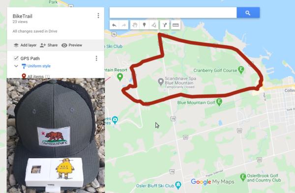
Here is a great weekend project, if you are into trekking or taking long bike rides, and need a GPS data logger to keep track of all your treks/rides you taken…
Once you have completed the build and downloaded the data from the GPS module of the trail, you can save the same using Google maps for future reference and comparison, and also share the same with your friends/family who came along, using the share button on Google maps.
To complete this instructable you will need an GPS receiver module, a micro-controller with serial interface and a Lipo battery. I am using a Flora as the micro-controller and wearable Flora GPS from Adafruit. In addition you will need a laptop with Adafruit’s version of the Arduino IDE to upload code to the Flora board.
Step 1: Things You’ll Need to Complete the Build
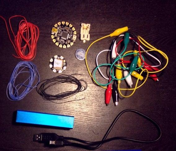
Here are the electronic components you will need to complete the build
- Adafruit Flora
- Flora GPS receiver
- Coin Cell battery holder Coin cell CR2032 (3V)
- Lipo Battery 2000 mAh
- Lipo charger
- Hook up wire(30AWG wire is the best or you can also use breadboarding wire)
- USB portable charger
- Mini USB cable
Download the STL files attached in the next step and 3D print the parts, i am using Flashforge Creator Pro as a 3D printer filament, and using 1.75 mm white PLA filament.
Tools you’ll needed
- Soldering Iron and Solder
- Scissors/Crimping tool
- Double sided stick Foam tape
- Alligator clips to test the circuit first before solde
Step 2: 3D Printing
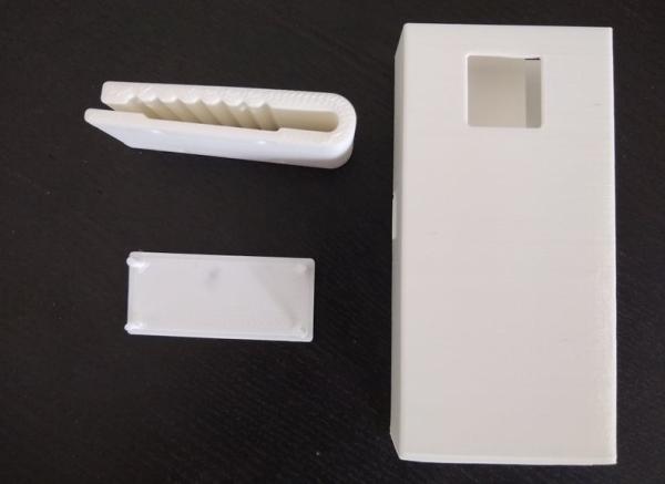
Download the STL files attached and using 3D printing software slice, and 3D print the files.If you don’t have a 3D printer handy you can use one at your local maker club, or library, or use a 3D printing service like 3D hubs.
In my case, I printed the STL files using the Flashforge creator pro and 1.75 mm white PLA. In addition, for slicing I am using Slic3r with the layer height set to 0.3mm and fill density to 25 %. All the parts should take about 4 to 5 hours to 3D print, and will depend on your 3D printer and slicer settings.
Step 3: Testing the Circuit
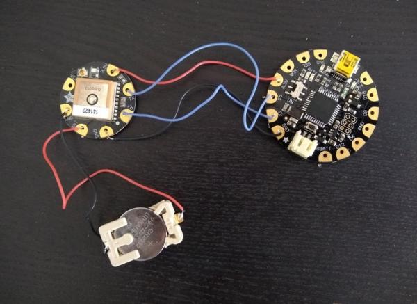
It is always a good idea to do a dry run of you circuit before you solder all the part together.Use the connections below, and use alligator clips connect the circuit.
- Flora 3.3V to GPS 3.3V
- Flora RX to GPS TX
- Flora TX -> GPS RX
- Flora GND -> GPS GND
- GPS BAT -> positive coin cell battery terminal
- GPS GND -> negative coin cell battery terminal
To upload code to the Flora board using the USB cable, you will have to download Adafruit’s version of the Arduino IDE and install it on you computer. For complete details on how to follow the link – https://learn.adafruit.com/adafruit-arduino-ide-setup/arduino-1-dot-6-x-ide
In addition, as part of the setup you will also have to download the GPS library from the following link – https://github.com/adafruit/Adafruit_GPS
Place the downloaded library in the /Arduino/Libraries folder and rename it to “Adafruit_GPS” restart your IDE. Now reopen your IDE and upload the example sketch to test your circuit, and open the serial monitor as shown in the picture above
According to the serial monitor you should see today date, number of satellites the GPS module has latched on to, which in my case is 7, and you should also see your location data that you can covert and add to google maps, to see that your current location is correct.
If the red light on the GPS module is blinking it means the module is still searching for a satellite, only once it stops blinking it means the GPS receiver has found a satellite.
Step 4: Upload Sketch to Log Location Data
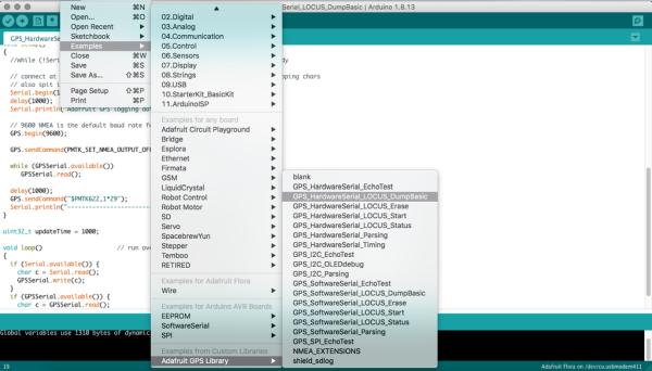
To upload the code/sketch to log location data, go to File > Example >Adafruit GPS -> GPS_HardwareSerial_LOCUS_Status.ino
Once the program loads connect the Flora with the USB cable and upload the sketch by hitting the Upload button (or use File > Upload). Now you can take the GPS box for a test drive,drive for at-least a couple of miles. In my case I drove to my favourite coffee shop and completed my weekly shopping at the local super market.
Note: The GPS receiver module used has built in data logging, and if you go through the code carefully you will observe that the Flora microcontroller board is used to send the start logging command.And the GPS receiver module can store about 16 hours of data.
Also for you next trek/bike ride it is a good idea to delete the GPS data logged, before heading out using – GPS_HardwareSerial_LOCUS_Erase.ino
Step 5: Putting 3D Parts and Electronics Together
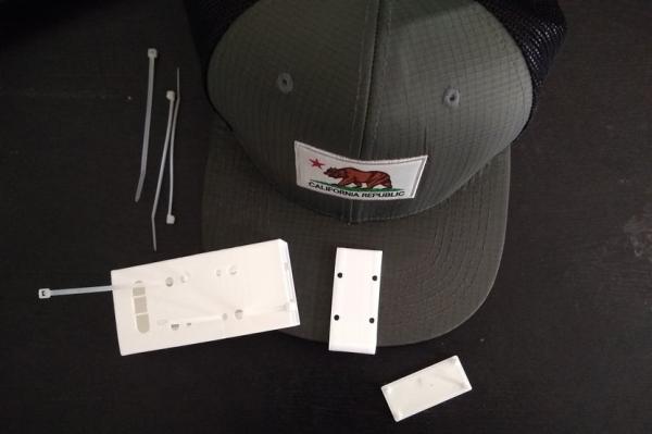
To put the 3D printed parts and electronics together, first start by attaching the Cap hook 3D printed part with the Box part, you can use 4 zip ties, but I found a couple of zip ties in the opposite direction should do the trick.
In the lower compartment of the box insert the coin cell battery holder and the Flora, and in the top first insert the lipo battery followed by the GPS.
Once done you can close the lip, which should snap fit in place, but I would suggest using a hot glue/ tape to secure the lid to the box.
In addition, the Lipo JST end of the flora should be pointing toward top so that it can inserted and removed easily for charging with a lipo charger.
Step 6: Upload Sketch to Get Logged Data

Now once your back home from your test drive, connect the device to your laptop and fire up the Adafruit’s version of the Arduino IDE Go to File > Example >Adafruit GPS -> GPS_HardwareSerial_LOCUS_DumpBasic.ino. Once the program loads connect the Flora with the mini USB cable and upload the sketch by hitting the Upload button (or use File > Upload)
Now click on the Serial Monitor as show in the picture above. And, copy the all the data into text editor and paste it in Locus Parser using the URL below –https://learn.adafruit.com/custom/ultimate-gps-parser, only copy and paste all the text after the ——‘s and ending with $PMTK001,622,3*36 .
Click the parse button below the first text box , and copy the KML output and paste it in any text editor as show in the screen shot above and save it with .kml extension.
In my case, the Locus Parser was not working, which meant I had to use the python program – log_to_kml.py to convert the serial monitor out put to a KML file, you can find more details at – https://github.com/don/locus
Source: GPS Cap Data Logger
- How do I test the circuit before soldering?
Use alligator clips to connect the Flora and GPS pins according to the specified wiring diagram without soldering. - What software is required to upload code to the Flora board?
You must download and install Adafruit's version of the Arduino IDE on your computer. - Does the GPS receiver have built-in data logging capabilities?
Yes, the module has built-in data logging and can store approximately 16 hours of data. - How can I view my tracked location on a map?
Copy the serial monitor output into Locus Parser or a Python script to generate a KML file, then open it in Google Maps. - What should I do if the red light on the GPS module is blinking?
A blinking red light indicates the module is still searching for a satellite; wait until it stops blinking. - Can I share my trek data with friends and family?
Yes, you can save the data using Google Maps and use the share button to send it to others. - What sketch should I use to clear previous data before a new trip?
Use the GPS_HardwareSerial_LOCUS_Erase.ino sketch to delete logged GPS data before heading out. - Which library must be added to the Arduino IDE for this project?
You need to download the Adafruit_GPS library from GitHub and place it in the /Arduino/Libraries folder. - How long does it take to 3D print the parts for this project?
The parts typically take about 4 to 5 hours to print depending on the printer and slicer settings. - What file extension should I use when saving the converted location data?
You should save the converted output file with a .kml extension.