
Summary of GPS Data Logger with Wireless Trigger Using Atmega644
This project built a portable GPS data logger with two modes: timed-interval logging and wireless-triggered logging (for correlating photos with locations). It uses an ATmega644 MCU to parse NMEA GPS data from a Navman Jupiter 12, display coordinates on an LCD, and store records to an SD card via SPI. A Radiotronix 433 MHz transmitter/receiver pair provides wireless triggering tied to a camera shutter. The system is battery powered (9V) and designed for removable SD storage and later mapping in tools like Google Earth.
Parts used in the GPS Data Logger with Wireless Trigger:
- ATmega644 Prototype Board
- Navman Jupiter 12 GPS Receiver (TU35-D420 series)
- SD Card and Socket
- LCD
- Radiotronix RCT-433 Transmitter
- Radiotronix RCR-433 Receiver
- Camera
- MAX233 and RS232 serial port connector (for debugging)
- LM340-T5 voltage regulator (replaced LM340LAZ-5)
- 9V battery clip and DC supply plug
- Active GPS antenna (L1 frequency, 1575.42 MHz)
- Two parallel 75Ω resistors (current limiting for antenna preamplifier)
The goal of this project was to create a portable GPS logger that could be wireless triggered by an external device, such as a camera.
Our device that we have designed operates in two modes. The first works as a basic GPS logger, which records GPS position information at timed intervals. The second mode only records position information when triggered manually over a wireless interface by an external device. The data is stored to an SD card, which can be removed for viewing the data on a computer. This can then be used with programs like Google Earth to display a map of the route traveled over the logging period, or in the case of using the external trigger with a camera, to correlate pictures with location information.
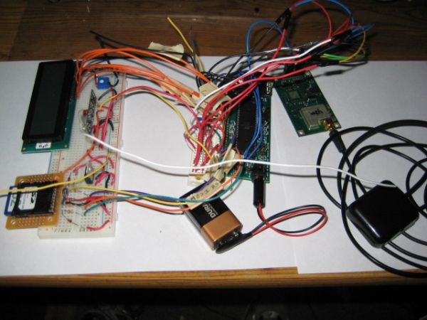
With GPS technologies becoming much more affordable and available these days, there are many new applications to which it can be applied. One particular application that interested us was logging location data, especially with respect to photography. Geotagging is the process of adding location information to the metadata of digital photographs. Web sites such as Flickr can use this information to display such photographs on an interactive map. Having taken thousands of photographs over the past couple of years, on trips such as Jeff’s travels around Australia and New Zealand, this type of technology would be very helpful in organizing all of this information. Some expensive cameras include this functionality, but most do not. In those cases, a log of position information over time could be correlated against the time stamps on the photographs to add this information after the fact.
High Level Design
The high level structure of our design uses multiple sources to interface with the ATmega644 MCU. We receive our GPS positional data from a Navman Jupiter 12 GPS receiver module. The module does all of the positional calculation, and outputs this information to the uart of the MCU using the NMEA 0183 standard. We parse this data, and display the positional latitude and longitude coordinates to the LCD. We read from the SD card at start up to see which mode we’re operating in. If it’s just logging mode, then we write the data from the GPS module to the SD card at timed intervals. If it’s trigger mode, then we write the data from the GPS module to the SD card every time we get a trigger from the wireless receiver. The wireless receiver gets a spike in its output when we press the trigger button on our wireless RF transmitter. This trigger button also is connected to a camera, which takes a picture when we press it. The data stored on the SD card can then be used to generate routes, or correlate pictures with locations, using preexisting software for Google Earth.
Standards Relevant to Project
- Since the device utilizes the Global Positioning System (GPS), its operation will be governed by IS-GPS-200D, the specification of GPS signals and operation. The details of this specification will not be directly used in this project because GPS acquisition and tracking will be handled by the module chip.
- The serial interface between the GPS module and the microcontroller is determined by NMEA (National Marina Electronics Association) standard 0183.
- The SD memory card is accessed over an SPI interface as dictated by the standards of the SD Association.
Hardware Design
The hardware for our design is comprised of the following:
- ATmega644 Prototype Board
- Navman Jupiter 12 GPS Receiver
- SD Card and Socket
- LCD
- Radiotronix RCT-433 Transmitter
- Radiotronix RCR-433 Receiver
- Camera
ATmega644 Prototype Board
The ATmega644 is responsible for coordinating data flow between all of the other hardware components. We built the prototype board to use the ATmega644 on, and also attached the MAX233 and RS232 serial port connector to use for debugging purposes. We also used the LED on the prototype board as a helpful tool to blink every time we wrote GPS data to the SD card. The one thing that we changed with the board was to replace the LM340LAZ-5 voltage regulator with the LM340-T5 voltage regulator. We did this because the output current on the LM340LAZ-5 was only 100mA, and we needed more than that for the GPS receiver. The LM340-T5 fixed this issue because it has an output current of 1A, which was sufficient to run our GPS receiver with.
We used the transmit and receive jumpers on the prototype board to switch back and forth between receiving data from the GPS simulator through the serial port, and receiving data from our actual GPS receiver with the output of the receiver connected directly to the receive pin. Doing this allowed us to still use the transmit pin to send debugging information through the serial port to HyperTerminal.
To make our device portable, we obtained a battery to DC supply plug, and a 9V battery clip so that we could power our prototype board off of a 9V battery. This battery supply also powers the GPS receiver, SD card, LCD, and RCR-433 receiver through their interfacing with the prototype board. Through testing, we’ve found that the battery life on a 9V battery with our circuit is about 3 hours of operation.
Navman Jupiter 12 GPS Receiver
The Navman Jupiter 12 is a 12-channel single board GPS receiver. This means that it’s capable of simultaneously tracking up to 12 visible satellites. The receiver can be powered from 3.3V to 5V, but we chose to power it with a 5V supply to ease interfacing with the ATmega644 and prototype board. Our particular receiver was part of the TU35-D420 series, which includes dead reckoning functionality. None of the dead reckoning functionality of this receiver was used.
The master reset line is tied high through a 57kΩ resistor as specified in the data sheet. The GPIO3 is similarly tied high to enable the module’s EEPROM for receiver settings rather than using the factory defaults. We connected the SDO1 output pin from the receiver to Pin D0, which is the uart receive pin, on the ATmega644.
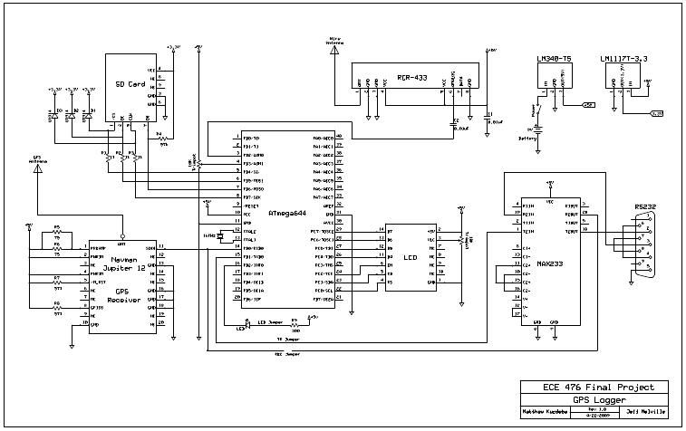
The receiver has an OSX/MCX connector for an antenna. The receiver supports both passive and active antennas, with an optional preamplifier for active antennas. The datasheet specified that a current limiting circuit was required if the preamplifier was used to prevent more than 100mA from passing through the preamplifier in the event of a short circuit. This was accomplished using two parallel 75Ω resistors on the power input to the preamplifier.
The antenna that we chose to use was an active GPS antenna at the L1 frequency of 1575.42 MHz. It can be powered from 3.0 to 5.0 V, and has a gain of approximately 30 dBi. We chose this antenna due to its high gain, low price, and availability.
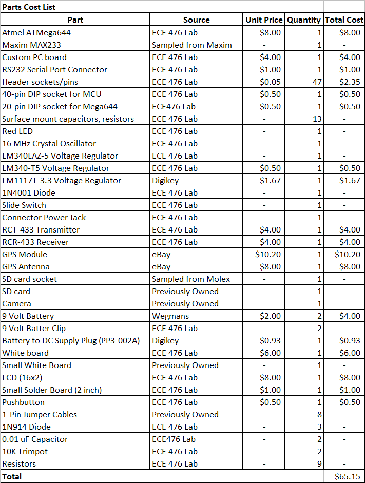
Parts List:
For more detail: GPS Data Logger with Wireless Trigger Using Atmega644
- What are the two operating modes of the device?
Timed-interval GPS logging and wireless-triggered logging. - How is GPS data received by the microcontroller?
Via the Navman Jupiter 12 output over a UART using the NMEA 0183 standard connected to the ATmega644 receive pin. - Where is the logged data stored?
On an SD card accessed over an SPI interface. - How is the wireless trigger implemented?
Using a Radiotronix RCT-433 transmitter and RCR-433 receiver; the receiver outputs a spike when the transmitter button is pressed. - How is the device powered for portable use?
From a 9V battery using a 9V battery clip and DC supply plug powering the prototype board and peripherals. - How long does the device operate on a 9V battery?
About 3 hours of operation in testing. - What role does the ATmega644 play?
It coordinates data flow, parses GPS NMEA sentences, displays coordinates on the LCD, and writes data to the SD card. - How does the project correlate photos with location?
The transmitter trigger is also connected to the camera shutter so logged GPS entries can be matched to photo timestamps. - Why was the voltage regulator changed on the prototype board?
The LM340LAZ-5 only provided 100 mA; it was replaced with the LM340-T5 which provides 1 A to supply the GPS receiver. - What antenna was chosen and why?
An active L1 antenna (1575.42 MHz) with ~30 dBi gain for high gain, low price, and availability.
