Summary of GPS Monitoring With OLED Display Project
This project integrates an ATGM332D GPS module, ATSAMD21J18B microcontroller, and SSD1306 128x64 OLED on a custom Eagle PCB, programmed with Atmel Studio 7 and ASF4. It demonstrates PCB design, soldering, ASF4-based USART NMEA parsing (GPRMC used), SPI display control, USB/CDC option, SWD programming, and basic enclosure planning. Operation shows reliable GPS fixes in 20–30 seconds outdoors; suggested improvements include relocating SWD, battery power, USB CDC support, antenna options, and adapting SSD1306 driver for 128x64.
Parts used in the ATGM332D GPS module project:
- ATGM332D GPS module
- ATSAMD21J18B microcontroller (TQFP64)
- SSD1306 0.96 inch OLED display 128x64 (SPI)
- USB connector (5V power and optional CDC)
- SWD 1.27mm 10-pin header
- Backup CR1220 coin cell battery
- GPS antenna (active antenna used)
- LEDs (Green, Orange, Red)
- LDO voltage regulator
- Various passive components (resistors, capacitors)
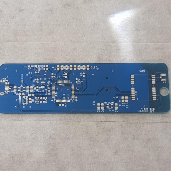
- PCB manufactured from Eagle design (100 x 31 mm)
Hello everyone, in this quick article I will share with you my project :ATGM332D GPS module with SAMD21J18 Microcontroller and SSD1306 OLED 128*64 display, I built a special PCB for it on Eagle Autodesk, and program it using Atmel studio 7.0 and ASF4 so in this article I will share with you this journey and the files I used if you are interesting to do it by yourself.
Now if you are programming your MCU/development board using Arduino , this project should be relatively easy to you , but here I will use ASF4(Advanced software framwork 4) from Atmel/Microchip which is based on C language and would give you an idea for how to read the GPS NMEA message using USART Asynchronous driver (Callback) and provide you with a simple library that you can use it with any Micro-controller and different platform by simply add the appropriate Driver you are using to receive the message from the GPS(NMEA message).
I will divide this article to:
- PCB Design.
- BOM you need to assemble the PCB
- Quick look to the software and the code itself and a test for the hardware and software.
- lastly but not least some point of improvement for this project.
You will find all the material related to this project onGithub ( Here )
Step 1: PCB Design Using Eagle
This project mainly based around ATGM332D GPS Module , simple GPS to use since it only needs a couple of passive components to work, and we could add a backup battery to save the time/date if we shutdown the main power source from the module.
and to control all the signals in the circuit I went with ATSAMD21J18B microcontroller , TQFP64 package since it has 128KByte of program memory storage and 32KByte of data memory (and I have a plenty of them laying around my workbench).
the circuit shall be powered by USB 5V source , also the USB can act as virtual COM port (CDC USB) and you can add a code for it if you want to communicate with the device through USB.
for the display I selected SSD1306 0.96′ OLED display with SPI bus , it’s small but it’s the suitable for the PCB size I wanted, the board dimension 100×31 mm.
programming the Microcontroller will be through SWD programmer (I use Atmel ICE ) and will connect it through 1.27mm 10p pin header.
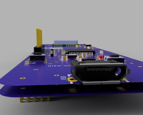
also I used Fusion360 to get a 3d view for the board and you can see some rendered image for it as well.
Step 2: Soldering the PCB
You have the choice to order a stencil with your PCB , it’s easier to apply the solder paste on the board using the stencil , I used hot plate to solder the components together , using hot air is also OK but be careful while soldering the LED since they are so sensitive to heat.
soldering the bottom side is a bit easier since it has only the SWD pin header and the backup battery , which you can solder them using soldering iron.
before you connect the circuit with any USB power source, check for any short circuit.
connect your GPS antenna and make sure you solder it’s connector properly, I fixed the antenna on the bottom side of the board.
Step 3: Software … Functionality…results
The software will be divided into 4 parts:
- USART to communicate with ATGM332 GPS module.
- SPI to communicate with OLED.
- USB CDC.
- GPIO to control LEDs
first connect the USB connector to power on the Circuit and then connect the ribbon cable with SWD connector.
Download the Code from github(Link here).
to get the Geo-Location you have 3 different NMEA messages options:
- GPGGA
- GPRMC
- GPGLL
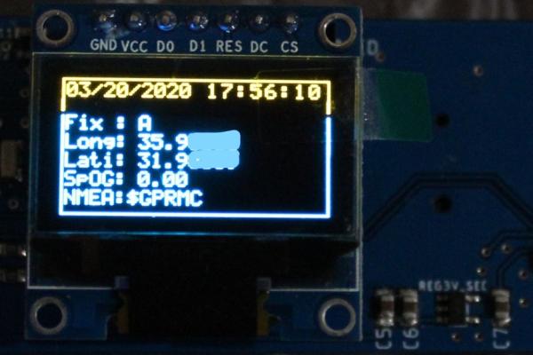
I used GPRMC sentence to obtain the location , time and date (time is 0.0 GMT) so in the code you will find:
GPRMC.Enable=1;/*0 if no need for this message*/
GPGGA.Enable=0;/*0 if no need for this message*/
GPGLL.Enable=0;/*0 if no need for this message*/
you can enable them all together and read them at the same time get the data you need.
once there is a valid GPRMC sentence , theGPRMC.Ready will become 1 and you can obtain all the data available in this sentence , check this link to see the data available in this sentence.
simply if Fix is ‘A’ that’s mean the Location are available , if Fix is ‘V’ that’s mean the location is not available.
notice that ATSAMD21 has internal RTC , but here I don’t use it and instead I use time and Date directly from the GPS, so if you don’t want to use the CR1220 Backup battery , once you disconnect the USB power source you will lose the Time/Date and for the next time you power on the circuit the time/date area on the display will be empty until the GPS has a valid time/date value.
the display will show you the current status of the GPS and will show the Geo-location once it’s available, however there are 3 LEDs on the Board:
- Green LED connected to PA06 , and will blink if there is a valid Geo-location value.
- Orange LED connected to PA07 and will blink once a second if there is no valid Geo-location.
- Red LED this one connected to PPS pin of the GPS Module and will blink only when there is a valid signal related to the Location.
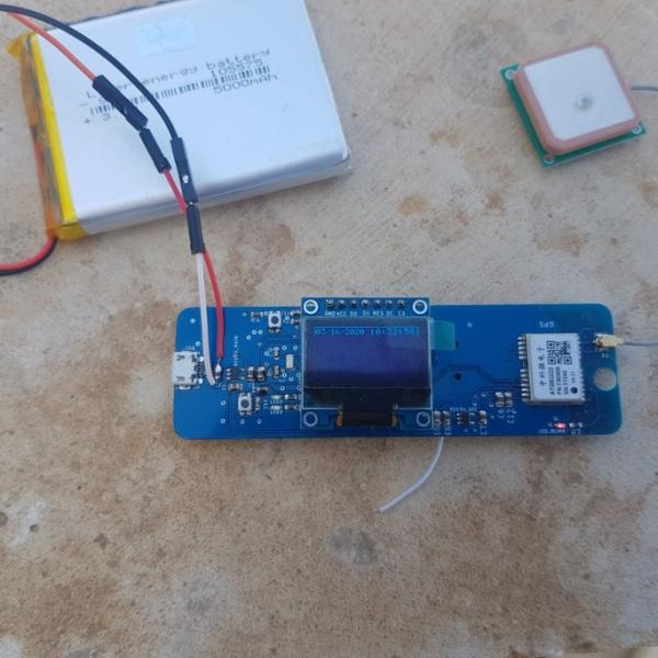
Results:
The circuit worked very well with me , get the Geo-location from the GPS took 20-30 seconds outdoor with clear sight to sky and between buildings without any problem even with antenna on the bottom side of the board.
Step 4: 3D Printed Case… Sort Of
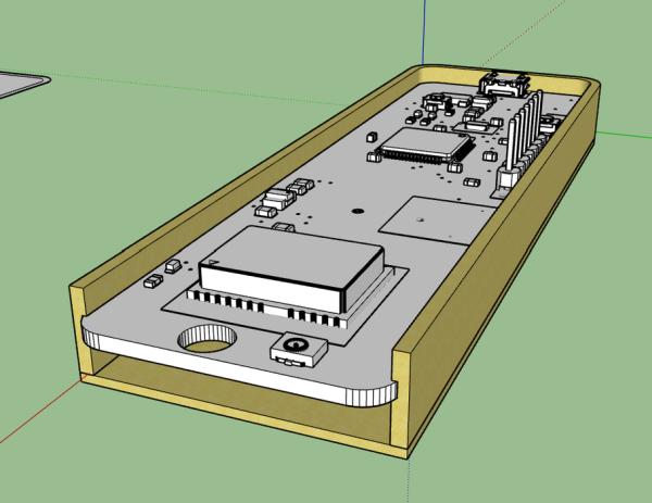
I prepared a simple case (more precise holder) for this circuit but because of COVID-19 epidemic and the lockdown I’m in right now , I couldn’t reach my 3d printer to print it, so I will update this section with stl file and a photos for the holder once it’s available.
Step 5: Things to Improve…
- Moving the SWD connector to the top side since it’s easier to connect it with your programmer.
- Powering the circuit from Lithium battery, I did it by soldering a jumper and it worked fine , bare in mind that the Linear (LDO) regulator has V drop voltage if the (Vbat – Vout) less than the Vdrop limit the circuit might not work properly .
- making a user button a bit bigger so it will be easier to press.
- adding USB CDC code so you can communicate/design a special program for MAC/PC/linux.
- For the GPS antenna, I used Active antenna for this project, using a passive antenna is a possible, by adding Low noise op-Amp like AT2659 (check also the schematic on ATGM332 Datasheet P.14).
- for OLED 0.96′ SSD1306 , the official library from microchip originally for 128*32 display , to modify the code to work with 128*64 you have to go to ssd1306.c and modify the code (check the image).
Source: GPS Monitoring With OLED Display Project
- Can I program the microcontroller using Atmel Studio?
Yes, the project is programmed using Atmel Studio 7 and ASF4 as described in the article. - Which NMEA sentence is used to obtain location, time and date?
The GPRMC sentence is used to obtain location, time and date in this project. - Does the project use the ATSAMD21 internal RTC for timekeeping?
No, the project uses time and date directly from the GPS rather than the internal RTC. - How is the OLED display communicated with?
The SSD1306 0.96 OLED is connected using the SPI bus. - How long does it take to get a GPS fix outdoors?
The project typically obtained a geo-location fix in 20 to 30 seconds outdoors with clear sky view. - What indicates a valid or invalid GPS fix on the board?
Green LED blinks for a valid geo-location, Orange LED blinks once per second when no valid geo-location, and Red LED blinks on PPS when valid location signal exists. - Can the board be powered from a battery?
Yes, powering from a lithium battery is possible; the article notes using a jumper and warns about LDO dropout voltage considerations. - Is the SSD1306 library ready for 128x64 display?
The official Microchip SSD1306 library was for 128x32; you must modify ssd1306.c to support 128x64 as mentioned in the article.