Summary of HackerBox 0044: PCB 123
HackerBox 0044 is a subscription kit focused on PCB design, AVR/ATtiny85 programming, serial RGB LEDs, and a Pro ESP32 WiFi + OLED module. The box includes components and kits (SIMON SAYS badge, prototype board, Pluggable ATtiny dev board) plus tutorials for programming via Arduino IDE, USBasp, Arduino as ISP, or ESP32 as ISP, PCB creation resources, and assembly/programming steps for the SIMON SAYS badge.
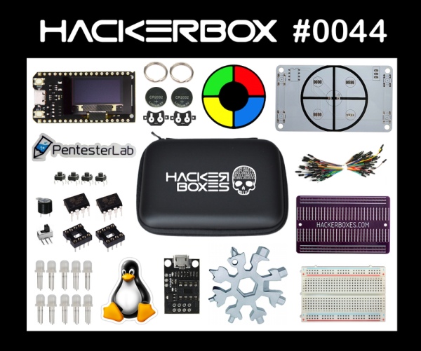
Parts used in the HackerBox 0044:
- Exclusive HackerBox Zipper Toolkit
- Pro ESP32 with OLED and WiFi
- Addressable RGB LEDs Round 8mm (APA106)
- ATtiny85 Microcontrollers (two 8pin DIP)
- ATtiny85 Pluggable Development Board
- Solderless Breadboard 400 Point
- Exclusive HackerBoxes Prototype Board
- Bundle of Various Length Jumper Wires
- Exclusive SIMON SAYS PCB
- Exclusive SIMON SAYS Overlay Decal
- 8pin DIP Socket
- Tactile Momentary Buttons
- Piezo Buzzer
- Right Angle Slide Switch
- CR2032 Coin Cell Clips
- CR2032 Coin Cells
- Snowflake 18-in-1 Multitool
- Tux Linux Decal
- PentesterLab Decal
Greetings to HackerBox Hackers around the world! HackerBox 0044 brings us PCB Design, AVR Device Programming, Serial RGB LED Applications, Pro ESP32 WiFi OLED Development, and much more. This Instructable contains information for getting started with HackerBox 0044, which can be purchased here while supplies last. If you would like to receive a HackerBox like this right in your mailbox each month, please subscribe at HackerBoxes.com and join the revolution!
HackerBoxes is the monthly subscription box service for enthusiasts of electronics and computer technology – Hardware Hackers – The dreamers of dreams.
HACK THE PLANET
Step 1: Content List for HackerBox 0044
- Exclusive HackerBox Zipper Toolkit
- Pro ESP32 with OLED and WiFi
- Addressable RGB LEDs Round 8mm
- ATtiny85 Microcontrollers
- ATtiny85 Development Board
- Solderless Breadboard 400 Point
- Exclusive HackerBoxes Prototype Board
- Bundle of Various Length Jumper Wires
- Exclusive SIMON SAYS Badge Kit
- Snowflake 18-in-1 Multitool
- Tux Linux Decal
- PentesterLab Decal
Some other things that will be helpful:
- Soldering iron, solder, and basic soldering tools
- Computer for running software tools
Most importantly, you will need a sense of adventure, hacker spirit, patience, and curiosity. Building and experimenting with electronics, while very rewarding, can be tricky, challenging, and even frustrating at times. The goal is progress, not perfection. When you persist and enjoy the adventure, a great deal of satisfaction can be derived from this hobby. Take each step slowly, mind the details, and don’t be afraid to ask for help.
There is a wealth of information for current and prospective members in the HackerBoxes FAQ. Almost all of the non-technical support emails that we receive are already answered there, so we really appreciate your taking a few minutes to read the FAQ.
Step 2: Pro ESP32 With WiFi and OLED
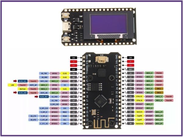
Features:
- ESP32 Tensilica Dual Core Processor
- Clocked at 240 MHz
- 520 SRAM
- 802.11 b/g/n Wi-Fi Transceiver
- Bluetooth dual-mode integrated traditional and BLE low-power
- 4MB (32 M bit) Flash
- 0.96-inch White OLED Display
- Lithium battery charging circuit and interface
- USB to serial bridge chip and MicroUSB port
The ProESP32 can be powered up by plugging it into a USB port. At that point, it will start running the pre-programmed OLED demo.
To (re)program the ESP32, we’ll use the Arduino IDE. If you don’t already have the IDE installed, get it here.
Next, follow the process for adding ESP32 Board Support into the Arduino IDE.
Next, instal this OLED display library into the Arduino IDE.
A good sketch to start with is the example SD1306SimpleDemo. Open that up and change the parameters passed into the display constructor for the OLED pins used on the module:
SSD1306 display(0x3c, 4, 15);
Also, flick the OLED reset pin (on I/O 16) by adding the following two lines just before the display.init() call in the setup function:
pinMode(16, OUTPUT);
digitalWrite(16, 1);
Program the modified sketch into the ESP and the OLED demo should appear.
Other projects to consider for the Pro ESP32 OLED module include:
Step 3: Serial Addressable RGB LEDs
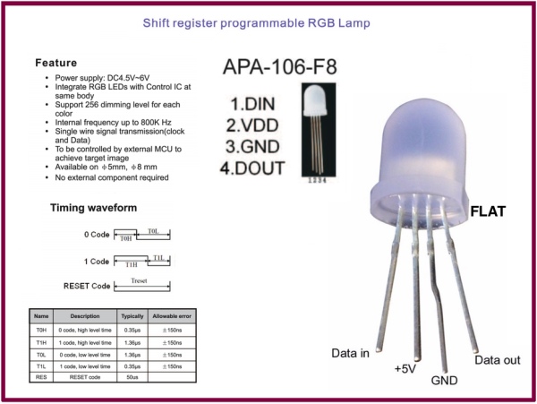
Serial Addressable LEDs can be chained together and controlled by ONE SINGLE PIN. Simply connect an I/O pin to the first LED’s “Data In” port and then connecting that LED’s “Data Out” port to the next LED’s “Data In” and so forth.
Grab one or both of these libraries to use the APA106 RGB LEDs with the ESP32, the ATtiny85, or any other Microcontroller of your choice:
A huge variety of other form factors of these sort of LEDs are available from Adafruit and elsewhere. They are a great option for any indicator or visual entertainment needs.
Step 4: ATtiny85 Microcontroller
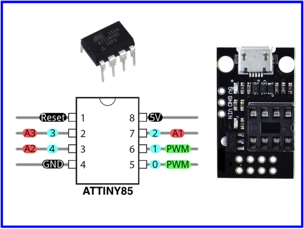
ATtiny (also known as TinyAVR) are a subfamily of the popular 8-bit AVR microcontrollers like those used in various Arduino boards such as the UNO and NANO. ATtiny MCUs typically have fewer features, fewer I/O pins, and less memory than other AVR series chips, but they are very tiny and easy to use.
The LED on the Pluggable Development Board is a breakout for the ATtiny devices. It features an ISP header for programming the MCU. Pin 6 (Arduino I/O 1) is wired to an LED. A MicroUSB port is wired to power the module and also support use as a Digispark if the microcontroller is programmed with the micronucleus bootloader.
Step 5: Programming ATtiny With USB ASP
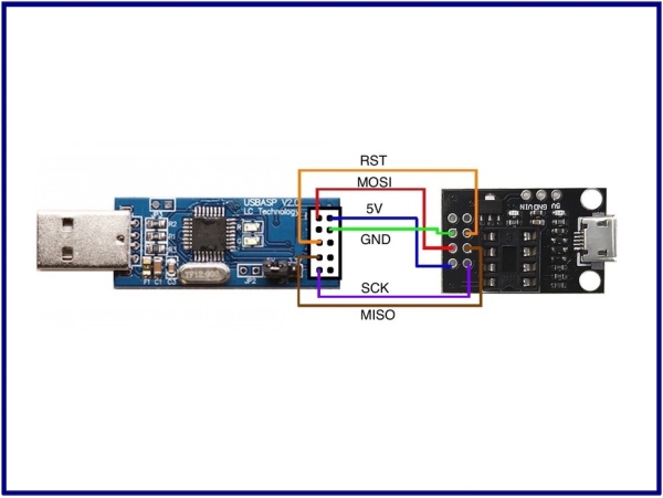
When a new, stock ATtiny85 chip (like the two 8pin DIP chips in this box) is purchased from Mouser or DigiKey, it is completely blank. The chips do not have micronucleus or any other bootloader on on them. They need to be programmed. For example using an ISP (in-circuit programmer).
USBasp is a USB in-circuit programmer for Atmel AVR controllers. It simply consists of an ATMega88 or an ATMega8 and a couple of passive components. The programmer uses a firmware-only USB driver, no special USB controller is needed.
Insert the ATtiny85 into the Plugable Development Board (mind the pin one indicator) and wire the board up the USBasp as shown here.
Add ATtiny support to the Arduino IDE (see details at High-LowTech):
Under preferences, add an entry to the list of board manager URLs for:
Under Tools->Boards->Board Mangers, add the board manager package from ATtiny by David A. Mellis.
This will add ATtiny boards to the board list supporting settings for”
Board: ATtiny25/45/85
Processor: ATtiny85
Clock: Internal 1 MHz
[IMPORTANT NOTE: Never set the clock to EXTERNAL unless the chip actually has an external clock source.]
Load the code example for “blink”
Change LED_BUILTIN to 1 in three places in that sketch and upload it to the ATtiny85 using USBasp.
The LED on the Pluggable Development Board should now blink.
Step 6: Programming ATtiny With Arduino
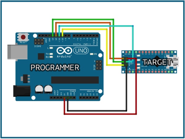
Any Arduino (UNO, NANO, or otherwise) can be used as an ISP (in circuit programmer) to program other Arduinos or even blank, stock AVR microcontrollers. Details for ArduinoISP can be found in the Arduino online docs under “Use Arduino as ISP”.
Step 7: Programming ATtiny With ESP32
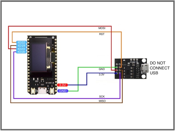
Just like an AVR-Based Arduino, an ESP32 module (such as the Pro ESP OLED) can be used as as an ArduinoISP. This modified version of ArduinoISP is available for use on an ESP32, which can be wired as shown here.
Step 8: Creating Printed Circuit Boards
A printed circuit board (PCB) mechanically supports and electrically connects electronic components or electrical components using conductive tracks, pads and other features etched from one or more sheet layers of copper laminated onto and/or between sheet layers of a non-conductive substrate. Components are generally soldered onto the PCB to both electrically connect and mechanically fasten them to it. (Wikipedia)
Screen captures were saved while creating the SIMON SAYS PCB included in this box. They are broken out into the following videos:
SIMON SAYS PCB (Part 1)
SIMON SAYS PCB (Part 2)
These videos feature a PCB created in EAGLE. Keep an eye out for a similar example video using KiCAD in the future.
Even more detailed resources:
Hackaday’s Series on Creating a PCB in Everything
Contextual Electronics PCB Tutorial Series
Example PCB Manufactures: PCBWay, OSH Park, JLCPCB, etc…
Step 9: Assemble SIMON SAYS Badge Kit
Kit Contents:
- Exclusive SIMON SAYS PCB
- Exclusive SIMON SAYS Overlay Decal
- ATtiny85 Microcontroller
- 8pin DIP Socket
- Tactile Momentary Buttons
- APA106 Addressable RGB LEDs
- Piezo Buzzer
- Right Angle Slide Switch
- CR2032 Coin Cell Clips
- CR2032 Coin Cells
Assembly Steps:
- DO NOT POPULATE THE BUZZER YET **
- Solder Coin Cell Clips – tinning all six pads
- Remaining components are populated on the front of the PCB
- Position Overly Decal onto PCB with red in upper left nearest Chip
- Puncture LED and Buzzer holes through decal from rear of PCB with a wire
- Note that the flat edge of the RGB LEDs face the Chip
- Solder Switch, LEDs, DIP Socket (without Chip), and buttons into place
** The buzzer is not populated yet because it shares the RESET pin of the Chip, so it not connected until later in the programming/assembly process.
Step 10: Program SIMON SAYS Badge Kit
Burn the attached “HBSimonBadge.ino” sketch into an ATtiny85 chip using the Pluggable Development Board.
In oder to use the NeoPixel library, we need to bump the internal clock rate from 1MHz to 8MHz under Tools->Clock. Remember to never set the clock to external unless an actual external clock is present.
Whenever you make a change to the clock rate you have to perform a “Burn Bootloader” operation under tools, so do that now too.
The sketch comes up in a flash “attractor mode” until one of the button is held down for a second or two, then one single LED will blink indicating that the SIMON Memory Game has begun. Try to copy the pattern as it gets longer and longer. Once the piezo buzzer functionality is added in the next step, the game becomes even more engaging.
Step 11: Using ATtiny85 Pin One As I/O for Buzzer
Only once the simon sketch is correctly programmed and appears to be properly functioning do we disable the RESET pin allowing it to be used as an I/O pin for the Buzzer.
We only get to do this once and then the chip cannot be reprogrammed again, so be careful!
To disable the RESET pin, use avrdude with fuse parameters set for ATtiny85 default but with 8X clock divider OFF and RESET Disable ON.
Details for this (including a link to a nice fuse calculator) can be found here.
In our example, we went to a terminal or command window and entered:
avrdude -c arduino -p attiny85 -U lfuse:w:0xe2:m -U hfuse:w:0x5f:m -U efuse:w:0xff:m
Once avrdude reports success, but the ATtiny85 back into the SIMON and make sure everything still works. If so, you can now solder the Piezo Buzzer onto the board with the POS+ marking oriented away from the chip. Prepare to enjoy low-fi-audio delights while you play!
The detailed link above also explains how to “unbrick” the chip so that is can actually be programmed again after the REST pin is disabled. However, this is a bit of pain (requiring connecting up of a “high voltage programmer”) so we recommend just making sure the ATtiny85 is programmed as you wish before disabling the RESET pin at soldering in the buzzer.
If you notice any glitchy problems with the MCU, make sure the socket seating is solid (bend the pins in/out a bit to add tension if necessary). If that doesn’t do the trick, you can tack a 0.1uF ceramic cap between the chip’s power and ground pads on the back of the PCB. We have not found the capacitor to be necessary, but having it there is technically considered good practice. On that note, you can also place a larger capacitor between VCC and GND as a board-level power smoothing measure.
Step 12: PentesterLab

Check out PentesterLab… Thanks for the stickers, guys!
A penetration test, colloquially known as a “pen test” or “pentest”, is an authorized simulated cyberattack on a computer system, performed to evaluate the security of the system. The test is performed to identify both weaknesses (aka vulnerabilities) and strengths, enabling a full risk assessment to be completed. (Wikipedia)
The National Cyber Security Center, describes penetration testing as, “A method for gaining assurance in the security of an IT system by attempting to breach some or all of that system’s security, using the same tools and techniques as an adversary might.”
Step 13: Hacklife++;
We hope you have enjoyed this month’s HackerBox adventure into electronics and computer technology. Reach out and share your success in the comments below or on the HackerBoxes Facebook Group. Also, remember that you can email [email protected] anytime if you have a question or need some help.
What’s Next? Join the revolution. Live the HackLife. Get a cool box of hackable gear delivered right to your mailbox each month. Surf over to HackerBoxes.com and sign up for your monthly HackerBox subscription.
Source: HackerBox 0044: PCB 123
- How do I start programming the Pro ESP32 OLED?
Install Arduino IDE, add ESP32 board support, install the OLED library, open SD1306SimpleDemo, set SSD1306 display(0x3c, 4, 15), toggle pin 16 before display.init(), and program the ESP32. - Can I chain the APA106 addressable RGB LEDs?
Yes; connect one I/O pin to the first LED Data In, then Data Out to the next Data In, and so on. - What libraries are recommended for APA106 LEDs?
Adafruit NeoPixel Guide and FastLED are recommended. - How do I program a blank ATtiny85?
Use an ISP such as USBasp, add ATtiny support to Arduino IDE, select ATtiny85 with Internal 1 MHz, load blink example, change LED_BUILTIN to 1, and upload via USBasp. - Can I use an Arduino as an ISP for ATtiny85?
Yes; any Arduino (UNO, NANO, etc.) can be used as an ISP following ArduinoISP instructions. - Can the ESP32 act as an ISP to program ATtiny85?
Yes; a modified ArduinoISP for ESP32 is available and can be wired to program ATtiny85. - Why is the SIMON SAYS buzzer not soldered initially?
Because the buzzer shares the RESET pin; it must remain until the chip is programmed and RESET is disabled for use as I/O. - How do I enable the ATtiny85 RESET pin as I/O for the buzzer?
After confirming the sketch works, use avrdude to set fuses disabling RESET and removing 8X clock divider, then solder the buzzer; the example avrdude command is provided in the article. - What should I do if the ATtiny85 behaves glitchy on the SIMON PCB?
Check socket seating, bend pins for tension, and optionally tack a 0.1uF ceramic cap between VCC and GND on the PCB back.