Introduction
The Haptic Appointment Manager manages all of an individuals appointments, ensuring they arrive on time and in the right location by subtly guiding them throughout the day.
This system uses a GPS receiver and a compass to maintain awareness of its absolute and rotational position. By interfacing with a calendar of time stamped waypoints, this system effectively guides the user to his appointments by vibrating in the direction of the next waypoint.
High level design:
Rationale:
People in general have a fairly poor sense of direction and are easily disoriented. While some people do have some sense of dead reckoning, it is questionably accurate and not present in all individuals. Additionally, since human direction finding is intrinsically tied to landmarks, vision impairment has the potential to seriously disorient an individual and make it extremely difficult for them to navigate from location to location. Though personal navigation systems do exist, primarily in cars or for sporting use, they are at best a crutch for a poor sense of direction. Since they use either visual or aural alerts to convey navigational information, they are inherently disruptive to the user. Additionally, the user is only aware of their navigational status when they are actively paying attention to the device. This is not reasonable for most users most of the time, particularly when the user is performing an intense activity.
Early in the course, Bruce mentioned prior work in haptic systems as providing an almost subconscious sixth sense. We decided that a similar system, providing constant navigational information could potentially create a system which would grant its user a perfect, non-disruptive sense of direction. Also, we noted that people are often late for things, and that coupling a navigation system with a scheduled calendar could be extremely useful. To this end, we designed a portable navigation system which interacts with the user entirely through a non-disruptive, haptic belt.
Our device takes a series of waypoints and vibrates in the direction the user needs to walk to reach their goal.
Logical Structure
This project was designed in an extremely modular manner. Early on, we decided on a list of functions that would be needed to use each hardware device. We also added functions that would be necessary for communications between each of the devices. Each hardware device was interfaced by a set of functions existing in their own file that could operate as a standalone program. These different programs were included as headers into a main program that joined them all together. Essentially, this code organization also reflected how the project flows. Essentially, each device was polled and the data was collected to achieve the result. This design strategy was used to essentially define a communication protocol within our project. This strategy proved very successful, as it allowed us to write and alter the code relating to hardware devices without altering the functionality of the overall project. Additionally, it allowed for incremental design and testing as components could be individually tested. Since the communication functions were defined, we could test components without using the rest of the file. When trouble shooting, we were able to view the output of each section and isolate the problem.
Background Mathematics
This project relied heavily on trigonometry and great globe navigation formulas. The following equation, which we found online returns the initial bearing needed to reach a second latitude and longitude pair. This formula is listed below.
This formula takes into account the curvature of the earth and the fact that the latitude and longitude are not strictly orthogonal to each other. However, in this context, it is not strictly needed as we are using very small distances.
For the compass, additional mathematics is needed to compute an angle from the two analog readings. Since the compass essentially outputs a DC value for both sine and cosine of whatever angle it is at, the angle is recoverable using arctangent. Since the angle is determined by the formulawhere the voltage1 and voltage2 are the signals from the compass.
Standards
RS232 Standard
We used a RS 232 standard for serial data communication between the GPS receiver and our microcontroller. Since our receiver is communicating directly with the microcontroller the voltage levels are of no concern (0 to 5 volts). Both devices have to be running at the same timing setup. The data is transmitted by first sending out a start bit then the data and finally a stop bit. No new data is transmitted unless there is a new start bit.
NMEA Standard
The data in the NMEA format includes the position, velocity and time sent out by the GPS receiver. Each line of data is a sentence that first contains a prefix that defines the device (GP for GPS receiver) followed by a character sequence that defines the sentence contents. Each sentence begins with a $ sign. This is followed by the UTC position fix, latitude in degrees/minutes, direction of latitude, longitude in degrees/minutes, direction of longitude, number of Svs, satellite ID number and an end character. The data transmitted is just contained in ASCII format. The NMEA standard for data transmission is 4800 baud.
Motorola Proprietary Binary Standard
The Oncore GPS receiver uses a special proprietary standard to display the information it receives from satellites. The Motorolla Bit Format standard does not follow the standard NMEA format so parsing the data is impossible without knowledge of the standard. After the searching the internet for a couple hours we were able to find information on the Motorolla binary format. The Receiver sends a status message that always begins with the character @@Ea and ends with a carriage return (<CR>) and a line feed (<LF>). The status message contains data regarding Date, UTC time, latitude and longitude position, velocity and a compass heading. The standard baud rate for this message is 9600 baud.
Patent, Copyright and Trademark Concerns
Our project uses a number of patented components as subcomponents. However, there appear to be no patent limitations on our overall design as we are using all of the devices as the manufacturer intended. Also, while both the Motorola proprietary binary standard and NMEA 0183 are described in copyrighted white papers, both standards are widely used and propagated in the minimal form we are using, including a number of open source projects. Our use here is clearly legal.
Hardware/software tradeoff
One of our more difficult tasks was to successfully interface with the compass. We could have avoided this by using a less accurate digital compass from the same company, but we ultimately decided the higher accuracy was worth the additional labor.
Detailed Design
Hardware
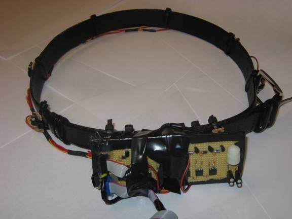
Belt:
The core user interactive component of the system was the vibrating belt. This effect was achieved by mounting eight small vibrators to the system. Each vibrator was designed to be individually addressable and to exhibit full speed control through pulse width modulation. The actual actuators used in this project were eight pager motors. The specifications for these motors indicated they were capable of operating in a range from zero to a maximum of four volts. At full voltage, the current draw of an individual motor was approximately 100mA. Each motor was mounted on a small piece of perforated board which provided a stable mounting surface as well as a convenient place to form electrical connections. The perforated board made connectivity easier, and also provided a rigid surface for the vibrator to turn against, spreading out the vibration into a wider region. Zip ties were then used to connect the perforated board to the belt. Due to the movable nature of the zip ties across the belt this enhanced our ability to dynamically reconfigure the belt for a users of varying girth as well as solidly connecting each motor. Each of the motors shares a common power wire (red wire) that was daisy chained around the belt. Additionally, each motor had its ground connected to a controlled pin which selectively connected to ground. This grounding was controlled by the microcontroller. The motors were powered by a battery pack that was attached to the belt. This battery pack used two AA batteries to provide approximately 3V to the motors. All eight of the motors also required external circuitry to drive them. The circuitry, similar to the result from lab 5, performed optoisolation as well as current buffering to allow the microcontroller to drive the motors. Each of the eight motors uses the same circuitry which consists of a 4N35 optoisolator, a 10,000 KΩ, a 1 MΩ resistor, 1N4001 Diode, .1F capacitor and NPN bi polar junction transistor. The optoisolator is used to isolate the microcontroller from any nasty spikes that could occur in our motor driving circuit.
Dinsmore analog compass
The Dinsmore analog compass was used in our project to give our belt a constant compass bearing. The compass acts as a basic Hall Effect sensor that varies its output in response to a change in magnetic field. The sensor essentially measures the horizontal component of the Earths magnetic flux field. The sensor has six pins on it. The sensor produces two output voltages in response to changes in magnetic field. The two outputs were the value of a sine and cosine curve respectively at the angle of the compass. Each output pin has a reference 5 volt voltage and a reference ground. Both output voltages were also low pass filtered to reduce noise in the signals. We used a basic passive RC low pass filter to filter the signals. We used a 5 F capacitor (two 10 F capacitors in series) and a 10,000 KΩ resistor for our filter. These signals were then immediately fed to the ADC of the microcontroller. An external Vref is attached to provide the reference voltage for the ADC.
Digital Compass and Filter
GPS

The final piece of essential hardware in our project was the Global Positioning System module. The system uses medium earth orbit satellites that transmit radio wave signals to attain their current location, time and velocity. The GPS system needs at least 4 satellites to solve for position in three dimensions in order to avoid large position errors. Specifically for our project we used the GPS to measure Latitude, Longitude, UTC time and the correct date. For our project we used two GPS receivers a Motorolla Oncore GPS receiver and the MAP 330 receiver. The Oncore receiver transmits data in the Motorolla Binary format. The receiver requires about five volts to run with an externally applied battery pack and draws about 100 A of current. The receiver also required an antenna to receive satellite signals. The antenna receives satellite signals at 1575.45 Mhz and requires 5 volts for optimal use. The Oncore receiver itself has 10 I/O pins. For this project we used 5 of the I/O pins on the receiver. We connected pin one (externally applied backup power) to two double A batteries, pin three (gnd) to ground, pin seven (1pps RTN) to ground and pin ten (TTL RTN) to ground. We received data from the receiver through pin eight (TTL TXD). The data transmit pin transmits data using TTL logic. Due to the inaccuracy of the Oncore receiver we decided to demonstrate our appointment manager using Professor Lands Magellan Map 330 GPS receiver. The receiver transmits data in the standard NMEA format and is transmitted to our microcontroller through its serial port after passing through a MAX233 level shifter.
Parts List:
| Device | Cost per unit | Number used | Total price |
| Atmega644 | Free sampled | 1 | $8.00 |
| Oncore GPS Receiver | $5.00 | 1 | $5.00 |
| Antenna | $8.00 | 1 | $8.00 |
| Null Modem Cable | Free (owned) | 1 | $0.00 |
| Max 233 Level Shifter | Free (Sampled) | 1 | $0.00 |
| Old belt | Free (Owned) | 1 | $0.00 |
| AA batteries | Free (Owned) | 4 | $0.00 |
| 9 Volt Battery | $3.00 | 1 | $2.00 |
| Dinsmore Compass | $20.00 | 1 | $20.00 |
| Pager Motors | $0.79 | 8 | $6.32 |
| Perf Board | Free (Owned) | 1 | $0.00 |
| Optoisolators | $0.00 | 8 | $0.00 |
| Battery case | $1.00 | 3 | $3.00 |
| Pins | $0.05 | 28 | $1.40 |
| NPN BJT | $0.00 | 8 | $0.00 |
| Total | $53.72 |
For more detail: Haptic appointment manager Using Atmega644