Introduction:
The Help Quit Watch is a watch that smokers can wear to help them quit smoking.
The Help Quit Watch contains a smoke detector that detects whenever the smoker smokes and plays an encouraging clip to help the smoker stop. It then records statistics about the smokers habit. In addition, since it replaces the typical wrist watch, it also keeps and displays time and also has an alarm function.

High Level Design:
Project Inspiration:
The project was actually inspired by a friend of the group, Helen. Helen had learned in class that most smokers fail to quit because of the lack of reinforcement and support. This has prompted various hot lines that smokers can call when they are having difficulties quitting, however, this is requires the smoker themselves to take action before they are reminded of their goal. This is where our project can come in. As a wrist watch, the user can always wear the watch without any additional hassle, but if they do smoke, they will be automatically reminded and supported. The main reason why we chose this project was that it not only challenged the skills we had learned in class, but also to apply these skills by building something very practical and useful. With the incredible large amount of smokers in the world, believe that our tool will help make the world a better place.
Overall Concept:
The Help Quit Watch can be separated into three main components: the user interface, smoke detector and power management. These three components all feed into the microcontroller, which then handles the information and communicates to the other appropriate components. First, the user interface consists of 5 push buttons, an LCD and audio speakers. The 5 buttons, 4 on the STK 500 and 1 external, allow the user to wake the watch up, view recorded statistics, view and set time and alarm. The Help Quit Watch would be able to display time, keep track of the time since that last time the user had smoked, keep track of the number of times they had smoked in the past week week, and have one alarm. The LCD displays the information that the user selects to view and the audio component either sets the alarm off or gives the encouraging message when the smoke alarm is set off.
The second is the smoke detector. The smoke detector is homebuilt using an IR emitter and detector. The voltage from the detector adjusts according to the amount of light being detected. This voltage is then compared to a reference voltage, high when the detector voltage is higher than the reference and low otherwise.
The third part is power management. As a wrist watch, power consumption is critical, thus it is important to not have the microcontroller on when there are no calculations needed. Thus, our group implemented an Real Time Clock that has memory for an alarm. Thus, the microcontroller is asleep under normal operating conditions and is only turned on if one of three contingencies happen: the user wants to view/change the time/statistics/alarm, smoke has been detected, or the alarm goes off. When the Mega32 is in sleep mode, the RTC keeps track of the time allowing us to significantly decrease the power consumption. Below is an overall diagram:
Standards:
The UL-217 standard specifies the requirements that must be met by smoke alarms. Our rudimentary smoke alarm does not meet this standard. However, it is not necessary for our smoke alarm to meet this regulation because this standard is meant for smoke alarms for fire safety in residential units whereas our smoke detector is not being used for a residential setting.
Program Design:
Overall Design:
The software for this lab has four main components. The most important component, task1(), is responsible for the scheduling and execution of many of the watchs most important features. These features include the MCUs time keeping, the handling of a smoke detection, the reading and handling of the four STK push buttons used, the LCD output of the MCU, and the handling of putting the MCU to sleep. Another important aspect of the software is the handling of the three external interrupts into the MCU. The software also is responsible for the voice outputs for both the watch telling the user not to smoke and for the wake up alarm. Finally, the software is responsible to keep the MCUs time synchronized with the RTCs time.
Task 1:
Task 1 runs every 100 ms and makes up the heart of the Help Quit Watchs software program. Each iteration of task 1 first reschedules itself to run in the next tenth of a second. The task also keeps track of the time so that the MCU does not have to constantly communicate with the RTC while it is awake. Time is kept by sequentially iterating tenths of seconds, the unit digit of seconds, the ten digit of seconds, and then so on all the way up to the unit and ten digits of years.
Task 1 then looks for a smoking flag which would indicate that the smoke detector interrupt has gone off. If this happens, it will record the time for the purpose of being able to calculate the time since the last time the user has smoked and also increments the number of times smoked this week. However, we realize that the same cigarette could cause the smoke detector to cause an interrupt multiple times, so we implemented a one minute timer to prevent the same cigarette from being counted as multiple times smoked. The smoking flag will also cause a speech clip saying, Dont smoke. Its bad for you, to play.
Task 1 is also responsible for the handling of most of the Help Quit Watchs user interface. This includes reading the inputs from the STK 500s four push buttons and outputting to the LCD. The functions of the four push buttons are as follows:
-Button 0: Set Time/Alarm On
-Button 1: Set Alarm Time/ Alarm On
-Button 2: Time Since Last Smoke/ Hours
-Button 3: Number of Times Smoked This Week/ Minutes
If Button 0 and Button 1 are pressed together, it will turn the alarm on or off and the LCD will read Alarm On or Alarm Off accordingly. If Button 0 is pressed at the same time as Button 2, the watchs time will be increased by one hour. If Button 0 is pressed with Button 3, the watchs time will be increased by one minute. Pressing Button 1 along with Button 2 or 3 will increase the time of the alarm by one hour or minute respectively and will output Alarm at <new time>. Pressing Button 2 alone will display the amount of time it has been since the last time the user has smoked. This is done using a helper function called lastSmokeCalc(). Pressing Button 3 alone will display the number of times the user has smoked during the current week. These push buttons all use Port A of the MCU.
Finally, Task 1 is responsible for detecting whether or not the MCU should be put into Power-Down mode. After a minute of inactivity, the variable sleepin will have a value of 0 and the microcontroller will be put to sleep. Every time the user interacts with the watch, however, the timer will be reset to sixty seconds.
External Interrupts:
Our project uses three external interrupts into the microcontroller. These three interrupts are the smoke detector going into INT0, the push button going into INT1, and the RTC interrupt going into INT2. The software for the watch uses an ISR to deal with each of these three interrupts. Each of these ISRs will wake the microcontroller up from Power-Down mode if needed. If the ISR wakes the microcontroller up, it will also load the time to the MCU from the RTC. Each interrupt also has a unique effect in addition to this. The smoke detector interrupt is responsible for setting the smoking flag high when it is run so that task 1 will know that smoke has been detected. The push button interrupt is responsible for turning off the wake up alarm if it is running. The RTC interrupt first determines which of the two RTC alarms as gone off. Alarm 0 on the RTC is used in our program as the watchs user-settable alarm. If this goes off, the watch will start the PWM to make it say Wake Up! until the user stops it. Alarm 1 is set to go off at midnight at the first day of every week. The purpose of this is to reset the counter for number of times smoked in the week.
Speech Output:
The speech in this project was handled in a very similar manner to the way it was handled in Lab 2. Speech is produced by updating OCR0 every timer 0 overflow. If the PWM is on, the output to OCR0 will be determined by one of two helper functions that synthesize a voice output from one of two DPCM tables. The function voice0() will play a clip saying, Dont smoke. Its bad for you, every time smoke is detected. The function voice1() will play a clip saying Wake Up until the push button is pressed stopping it.
The sound clips were originally recorded from this website. This sound clip was synthesized using the techniques listed on the ECE 476 website.
Communication with the RTC:
One of the most vital parts of this lab is keeping the times on the microcontroller and RTC synchronized. The communication with the RTC was done using SPI. Writing to the RTC was done by first sending the address being written to and then sending the data. For example, writing to the seconds register in the RTC would look like:
SPIout = (seconds10<<4) | (seconds & 0x0f);
PORTB.4 = 1; //CS high begins load
junk = spi(Wseconds);
junk = spi(SPIout);
PORTB.4 = 0; //CS low ends load
To read from the RTC, we first had to send the address to be read from and then take in the value at that address and interpret it. For example, reading from the seconds register in the RTC would look like:
PORTB.4 = 1; //CS high begins load
junk = spi(Rseconds);
SPIin = spi(0x00);
PORTB.4 = 0; //CS low ends load
seconds = SPIin & 0x0f;
seconds10 = SPIin>>4;
Communications with the RTC happen under three different circumstances. The first is the initialization of microcontroller program, when the RTCs time must be initialized by writing to each of its registers. The second situation where communication must happen is when the user changes either the time, alarm time, or turns the alarm on or off. When this happens, the change must be written to the RTC. Finally, the time must be read from the RTC when the MCU comes out of sleep mode. These communications will assure that the MCU and RTC times will match each other.
Hardware Design:
The hardware design can be separated into five main components: the smoke detector, the RTC, the LCD, the audio output and the push button. The overall final product looked like:
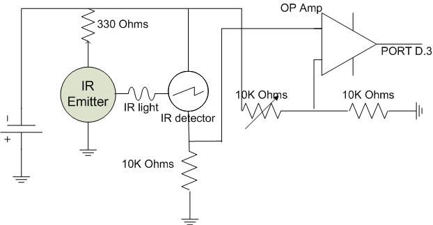
At first we wanted to reverse engineer a commercial smoke detector that we had purchased at Walmart, however, after attempting this for a few days and consulting TA’s we decided to build our own smoke detector. We decided use a simple IR emitter and detector combination as the basis of the smoke detector. The IR detector has an voltage output that reflects how much light it detects, around 2V with no obstructions and closer to 0V as less and less light is detected. Using this, the idea is to compare the voltage of the detector to a reference voltage that is calibrated such that if any of the light is obstructed from the detector, the voltage will drop below the reference voltage and the signal will go low. This low signal is then connected to INT1 on portD, thus allowing the smoke detector to externally interrupt the Mega32 and wake it up from sleep mode. Below is a circuit diagram of the smoke detector.
Parts List:
| Item | Quantity | Price/Per | Total Price |
| STK 500 | 1 | $15 | $15 |
| White Board | 3 | 6 | $18 |
| Power Supply | 1 | 5 | $5 |
| Mega 32 | 1 | 8 | $8 |
| LCD | 1 | 8 | $8 |
| B/W TV | 1 | 5 | $5 |
| RTC | 1 | 5.06 | $5 |
| 32KHz clk | 3 | 0.36 | $1 |
| LM386 | 2 | 0.94 | $2 |
| Commercial Smoke Detector | 1 | 4.99 | $5 |
| Total Cost: | $72 |
For more detail: Help Quit Smoking Watch Using Atmega32