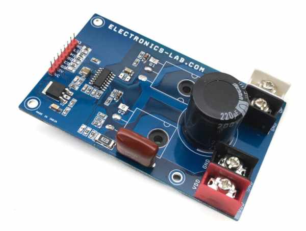
The project presented here is a versatile high voltage Half-Bridge with current feedback. The board is built using L6390 IC from ST Semiconductor. It is suitable for DC-DC converters, EHT drivers, induction heater drivers, battery chargers, LED drivers, DC motor speed controller and field-oriented control (FOC) motor driving application etc. The user can make a FOC Brushless motor driver with 3 of these units, Bidirectional Brushed DC motor can be controlled with 2 units. FDH3632 MOSFETs rated at 100V DC and 80A Current drive the output. Other High voltage and high current MOSFET can be used as per voltage and current requirements.

WeI have tested this board with 2A load and input frequency 10-80Khz. This project provides several more functions such as current feedback output, smart shutdown, fault shutdown etc. The board has two logic inputs, HIN and LIN, to separately control the high side and low side outputs, HVG and LVG. HIN is in phase with HVG, while LIN is out of phase with LVG. The signal inversion on the low side input allows control of the half-bridge output with only one control input signal. This board can work with double logic inputs or single input configuration. (See figure below for input configuration). Operating Load power supply 24V – 90V DC and logic supply 12-15V DC. U2 Regulator provides 3.3V DC output to drive Op-Amp circuitry and pull-ups. The board supports input signals 3.3V or 5V. Use large a size heatsink on MOSFETs for heat dissipation.
FEATURES
- Logic Power Supply VCC 12-15V DC
- Load Power Supply VDD 24V-90V DC
- Load 2 Amps (Change R17 Lower resistance and higher wattage for higher current Load)
- Current Feedback Output 2.250V without Load + (0.5V/1Amp)
- Inputs: HIN, 2.LIN, 3. Shutdown
- Outputs: 1. Current Feedback 2. Fault Output
- Input Signal HIN/LIN Frequency 10Khz – 80Khz Logic Level 3.3V/5V DC
- PCB Dimensions 98.90 x 60.33 mm
INPUTS (LOGIC INPUTS 3.3V/5V)
- HIN logic input: 85 kΩ (typ.) pull-down, R6 External pull-down Resistor.
- LIN logic input: 720 kΩ (typ.) pull-up connected to an internal 5 V regulator through a diode, R2 100K External Pull up Resistor
- SD logic input: 375 kΩ (typ.) pull-down, this pin required high logic input to enable the outputs. This pin goes low when fault condition occurs.
Read more: HIGH VOLTAGE HALF-BRIDGE WITH CURRENT FEEDBACK USING L6390
